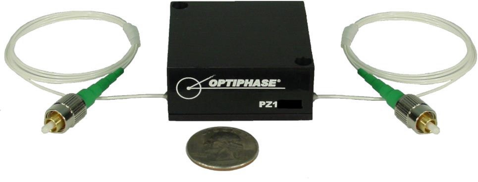
PZ1 Fiber Stretchers

Product information "PZ1 Fiber Stretchers"

High Speed; Fiber Type SM, PM, RC; 780-1625 nm; Fiber Length 5-17 m; Fiber Stretch 0.035-0.21 µm/V; Fiber Leads 1 m, 0.9 mm OD Jacket; Connector Type Bare Fiber, FC/PC, FC/APC

The PZ1 series are the high-speed members of Optiphase’s family of fiber stretchers. At the core of the PZ1 high-speed fiber stretchers is a fiber wound piezoelectric element for use in a wide range of optical interferometric measurement and sensing system applications.

Optiphase’s expertise in the design, manufacture and use of all-fiber interferometers has produced a unique multi-layer winding approach resulting in an enhanced modulation function while maintaining a high operational frequency. PZ1 high-speed fiber stretchers are available with single mode (SM), commercial polarization maintaining (PM, Panda or Bowtie) or SM reduced cladding (RC) fiber types

PZ1 high-speed fiber stretchers deliver a high performance to cost ratio, exceeding all other known competitive devices. The compact and low-profile form factor makes the PZ1 series easily configurable into small spaces.

In addition, Optiphase fiber stretchers are unique in that they do not require proprietary drivers. For most low-voltage applications (<±15 V), Optiphase stretchers can be driven by standard electronics such as signal generators, op-amps or other laboratory equipment without modification. For more information on how to drive PZ1 high-speed fiber stretchers see the downloadable application note.

Key Features:

  • High Speed
  • Compact Package
  • Fiber Type: Single Mode (SM), Polarization Maintaining (PM )or Reduced Cladding SM (RC) Fiber
  • Multiple Termination Choices
  • Unique Multi-layer Winding
  • Can Be Driven With General Purpose Electronics
  • Operational Wavelength: 780 to 1625 nm
  • Fiber Stretch: 0.035 to 0.21 µm/V
  • Optical Path Displacement (n = 1): 0.05, 0.2, 0.3 µm/V
  • Time Delay: 0.00017 to 0.001 ps/V
  • Fiber Length: 5, 12.3, 17 m Inclusive
  • Fiber Wind: 4 Layer (1 Layer PM Version Available)
  • Optical Loss: ≤0.5 dB
  • Maximum Voltage Range: ±500 V (Off Resonance, 1,000 V Peak-to-Peak)
  • Fiber Leads: 1 m, 900 μm Loose Tube
  • Connector Type: Bare Fiber, FC/PC, FC/APC
  • Dimensions: 50.8 x 50.8 x 21.6 mm

Applications: Open Loop Demodulation; Sensor Simulation; Variable Optical Delay; General Purpose Fiber Interferometry; Large-angle Modulation of Interferometric Phase

Manufacturer "Optiphase"
Related links of the manufacturer

Similar products

CAP Fused Silica Capillary Tubing
Inside Diameter 15 to 450 µm; Outside Diameter 90 to 673 µm; Coating Polyimide; Temperature Range -190 to +350 °C; Tensile Strength >600 kpsi Fiberguide’s fused silica capillary tubing is used for micro-fluidics applications and in gas chromatography (GC) separation columns. These capillaries are coated with polyimide for mechanical stability and versatile uses. With inert surfaces and high purity, Fiberguide’s capillary tubing solutions provide a very high phase stability, while their peak mechanical stability leads to greater yield and more cost-efficient tubing. Based on the great flexibility combined with high tensile strength (>600 kpsi), these capillary tubing solutions are pressure resistant to 4,500 psi and allow very small radii during coiling with no kinking. They are impervious to chemicals, allowing usage in harsh environments. A wide range of internal and external diameters with tight tolerances allows users to select a capillary tubing solution that best suits their flow rate requirements. All capillaries can be easily cleaved or cut, allowing to adjust exactly the column length needed for interfacing. While the mirror smooth inner surface provides stable laminar flow profiles and good adherence, the capillary tubing solutions’ Polyimide coating is very durable and abrasion resistant. Key Features: Pure Fused Silica Construction Outside Diameters: 90 to 673 µm Inside Diameters: 15 to 450 µm Coating: Polyimide Temperature Range: -190 to +350 °C Tensile Strength: >600 kpsi 100% Proof Tested for Strength Applications: Micro-fluidics Applications; Gas Chromatography (GC) Separation Columns
Product number: SW10708
Manufacturer:
De-Specklers
Wavelength 400 to 1550 nm; Fiber Types All Silica, Plastic Clad, Round or Square Core; Fiber Core Size 100 to 400 µm; Buffer Types Polyimide, Nylon, Tefzel, Acrylate; Power Supply 5 V Fiberguide’s proprietary de-speckler technology averages the modal noise within an optical fiber. This reduction in speckle is an ideal choice for fiber assemblies used in the life sciences, digital laser projection, interferometry, laser beam homogenization, lithography and metrology. For many fiber coupled applications, modal noise interferes with optimal performance. Fiberguide has developed a small and compact de-speckling system which maximizes performance and reliability. Key Features: Wavelength: 400 to 1550 nm Assembly Types: Single Fiber Assemblies Fiber Types: All Silica, Plastic Clad, Round or Square Core Fiber Core Size 100 to 400 µm Buffer Types: Polyimide, Nylon, Tefzel, Acrylate Connectors: 905/906 SMA, FC/PC,UPC,APC, ST/PC,UPC,APC, Cleaved/Polished Ends, Round 2.5 mm Ferrule, Custom 50 x 22.25 x 13.3 mm Power Supply 5 V Power Consumption 3 W Applications: Bioanalytical Instrumentation; Flow Cytometry; Gene Sequencing; Fluorescent Microscopy; Microscopy; Spectroscopy; Digital Laser Projection; Interferometry; Laser Beam Homogenizers; Lithography; Metrology
Product number: SW10707
Manufacturer:
Fiber Optic Delivery System for Flow Visualization
Delivery System consisting of a laser to fiber coupler, fiber optic patchcord, fiber optic collimator, and fiber optic line generator; Power Transmission ≤1 to ≤ 20 W In flow visualization systems, a visible wavelength laser beam is coupled into an optical fiber, recollimated at the fiber output, and then sent through a lens, generating a line. This line of laser light is then shone through the flowing liquid under inspection. Any particulate matter present, or changes to the flow pattern within the fluid, causes fluctuations in the output beam pattern which are visually observed. OZ Optics offers complete delivery systems for flow visualization, consisting of a laser to fiber coupler, fiber optic patchcord, fiber optic collimator, and fiber optic line generator. The line generator uses a Powell lens. Compared to simple cylindrical lenses, this Powell lens transforms a collimated beam into a line with a uniform output intensity along its entire length. Fiber optic delivery systems are available for a wide range of wavelengths. Other wavelengths are available on request. The maximum power transmission possible depends upon the fiber size chosen 4/125 fiber can handle 1 W to 3 W, 10/125 fiber can handle 3 W to 5 W, 25/125 fiber can handle 5W to 10 W, and 50/125 fiber can handle 10 W to 20 W. For best repeatability and stability, FC connectors are recommended for the fiber couplers and collimators. Pigtail style couplers and collimators are also recommended.By choosing different focal lengths for the collimating and Powell lenses, different line widths and fan angles are possible. Standard line widths for singlemode fibers are 0.8 mm and 1.2 mm. Standard fan angles are 10°, 30° and 45°. Contact us for further information on available line widths and fan angles. Key Features: Uniform Output Intensity over Entire Length Rugged and Compact Design Low Insertion Loss Visible Wavelength Range: 400 to 700 nm Wide Fan Angles Available: 10 to 75 degrees Applications: Flow Cytometry, Particle Measurement, Imaging Systems
Product number: SW10714
Manufacturer:
FORF Fiber Optic Reflectors
Fixed or Variable; Receptacle or Pigtail Style; Fiber Type SM, MM, PM; 400 to 1600 nm; Back Reflection 25 to 60 dB OZ Optics’ FORF series of fiber optic reflectors are used to reflect the light emerging from a fiber back in the reverse direction. They are used to build fiber interferometers, or with fiber fused splitters to measure back reflection within fiber optic components. They can also be used to measure the sensitivity of sources to back reflection from other devices, by providing reference reflection levels. This is very useful for deriving back reflection specifications for transmitters. Fiber optic reflectors consist of a fiber optic collimator and a mirror. The fiber output is first collimated, then it strikes the mirror and is reflected back into the collimator. The angle between the collimator and the mirror is adjusted using OZ Optics' patented tilt adjustment technique, until as much light as possible is reflected back into the fiber. Using this technique, reflectors with typical losses of only 0.6 dB can be constructed. A variable reflector is available that includes a blocking screw, to obtain variable reflection levels. This is achieved by partially blocking the collimated beam between the lens and the mirror. Both connector receptacle style and pigtail style reflectors are available. Connector receptacle style reflectors come with a female connector receptacle to allow the fibers to be easily changed. Pigtail style reflectors come with a fiber of your choice permanently attached to the collimating lens. This type of reflector is recommended for optimum coupling efficiency and stability. The other end of the fiber can be terminated with your choice of connector. OZ Optics also provides fibers with coated ends. Gold coatings are used to provide excellent broadband reflection for infrared wavelengths. Other coating materials are available for other wavelengths. The ends can have total reflecting, or partial reflecting/partial transmitting coatings. Contact AMS Technologies for further information. Reflectors are available for wavelengths from 400 to 1600 nm. Reflectors that operate at both 1300 and 1550 nm are available, with only a slight difference in insertion losses at both wavelengths. Broadband reflectors using achromatic lenses to collimate light at different wavelengths are available. Partially reflecting mirrors are also available, to partly transmit the light. The transmitted light can be coupled into an output fiber as an option, thus forming an in-line reflector. Contact AMS Technologies for further details. Key Features: Wide Range of Available Wavelengths Available in Single Mode (SM), Polarization Maintaining (PM) and Multi Mode Versions Low Insertion Loss Compact Housing Partial Reflectors Available Applications: Interferometric Sensors; Circulators; Return Loss Testing; Reference Beam Power Measurements
Product number: SW10866
Manufacturer:
FPS-001 Phase Shifter
980-1650 nm; Total Phase Shift >8π; IL <0.1 dB; RL >65 dB; PDL <0.05 dB; Residual Amplitude Modulation ±0.01 dB General Photonics’ FPS-001 is an all-fiber device that shifts or modulates phase by up to 15π at frequencies from DC to 20 kHz. The advantage of the all-fiber construction is that insertion loss and back reflection are reduced to near zero. Key Features: Low Insertion Loss (IL): < 0.1 dB Low Residual Amplitude Modulation: ±0.01 dB NoTail™ Version Available Operating Wavelength: 1260 to 1650, 980 to 1310 nm Return Loss (RL): >65 dB Total Phase Shift (0 to 20 kHz): >8π Half-wave Voltage (0 to 20 kHz): <20 V Polarization Dependent Loss (PDL): <0.05 dB Maximum Applied Voltage: 150 V Dimensions: 35 x 14 x 14 mm (Pigtail), 74 x 14 x 14 mm (NoTail™) Applications: Precision Phase Tuning or Phase Modulation in Fiber Interferometers, Sensor Systems, Fiber Laser Systems or Fiber Resonators
Product number: SW11304
Manufacturer:
FPS-002 Phase Shifter
780-1550 nm; Total Phase Shift >65π; IL <0.5 dB; RL >50, >55, >58 dB; PDL <0.05, <0.1 dB; Residual Amplitude Modulation ±0.01 dB Coherent or interferometric sensor systems, such as distributed acoustic sensors (DAS), often require a low-loss, low-cost phase shifter or modulator to obtain the desired sensing signals. General Photonics’ FPS-002 is an all-fiber device that shifts or modulates phase shifts up to 75π at frequencies from DC to 20 kHz. The FPS-002 phase shifter requires a lower half-wave voltage than the FPS-001 phase shifter module: only 2 V compared to up to 20 V. Like the FPS-001, it is an all-fiber design and offers the benefits of low loss and back reflection. Two different size packages (small frame or large frame) are available to accommodate the bend diameter requirements of different fibers. Key Features: Low Insertion Loss (IL): <0.5 dB (at λc, Excluding Connectors) Low Polarization Dependent Loss (PDL): <0.05 dB (SM), <0.1 dB (PM) Return Loss (RL): >58 dB (Without Connectors), >55 dB (With APC Connectors), >50 dB (With PC Connectors) Low Residual Amplitude Modulation: ±0.01 dB at 1550 nm Total Phase Shift (@500 Hz, Vpp = 150 V): >65π (@ 1550 nm) Low Half-wave Voltage (@ 500 Hz): 2.5 to 4.5 V Typical (Small Frame), 0.7 to 1.5 V Typical (Large Frame) Operating Wavelength: 780, 1060, 1310, 1550 nm Fiber Type: ClearCurve ZBL, HI1060, 780 HP, PM, PM980XP Capacitance of Piezo: 0.18 µF Maximum Applied Voltage: 150 V Compact Size: 35 x 17 x 10 mm (Small Frame), 45 x 27 x 11 mm (Large Frame) Applications: Fiber Interferometers; Fiber Laser Systems; Fiber Sensor Systems
Product number: SW11310
Manufacturer:
FPS-003 Phase Shifter
780-1550 nm; Total Phase Shift >55π; IL <0.5 dB; RL >55 dB; PDL <0.05 dB; Residual Amplitude Modulation ±0.01 dB General Photonics’ FPS-003 all-fiber phase shifter/modulator combines a wide modulation bandwidth (up to 60 kHz) with low half-wave voltages to create a long-range device that can be driven by standard function generators. Like General Photonics’ other phase shifters, it employs all fiber construction and has low insertion loss and back reflection. In addition to fiber sensor systems, this compact device is ideal for fiber laser systems, fiber resonators, and fiber interferometers for precision phase tuning or phase modulation. Key Features: Wide Frequency Range - Operating Wavelength: 780, 1060, 1310 or 1550 nm Low Half-wave Voltage Large Phase Shift Range Compact Size: 31 x 31 x 14.5 mm Low Insertion Loss (IL): <0.5 dB (at 1550 nm, Excluding Connectors) Return Loss (RL): >55 dB (Excluding Connectors) Low Residual Amplitude Modulation: ±0.01 dB (@ 1550 nm) Total Phase Shift (@500 Hz, Vpp = 150 V): >55π (@ 1550 nm) Fiber Type: ClearCurve ZBL, 780 HP, PM, Other Half-wave Voltage (Vπ @ 500 Hz): 1 to 3 V Typical Resonance Frequency: 36 to -39 kHz Typical Vπ at Resonance Frequency: <150 mV Typical Polarization Dependent Loss (PDL): <0.05 dB at 1550 nm Capacitance of Piezo: 5 to 12 nF Maximum Applied Voltage: 150 V Applications: Fiber Interferometers; Fiber Laser Systems; Fiber Sensor Systems
Product number: SW11311
Manufacturer:

Customers also viewed

PZ2 Fiber Stretchers
High Efficiency, Open and Enclosed Versions; Fiber Type SM, PM, RC; 780-1625 nm; Fiber Length 40-82 m; Fiber Stretch 3.8-8.0 µm/V; Fiber Leads 1 m, 0.9 mm OD Jacket; Connector Type Bare Fiber, FC/PC, FC/APC The PZ2 series provides the most extensive stretch of Optiphase’s stretcher product family. At the core of the PZ2 high-efficiency fiber stretchers is a fiber wound piezoelectric element for use in a wide range of optical interferometric measurement and sensing system applications. The PZ2 is ideal for use in OCT (Optical Coherence Tomography) and OCDR (Optical Coherence Domain Reflectometry) applications requiring scattering or boundary definition measurements. Optiphase’s expertise in the design, manufacture and use of all-fiber interferometers has produced a unique multi-layer winding approach resulting in an enhanced modulation function while maintaining a high operational frequency. PZ2 high-efficiency fiber stretchers are available with single mode (SM), commercial polarization maintaining (PM, Panda or Bowtie) or SM reduced cladding (RC) fiber types PZ2 high-efficiency fiber stretchers are available in two versions: Housed in an enclosure with connectors, making set-up and use quick and easy Bare lead fiber stretcher, not enclosed and including a convenient mounting kit consisting of a top-mount aluminum retainer and two silicone rubber pads - the mounting kit includes top or bottom mount Optiphase fiber stretchers are unique in that they do not require proprietary drivers. For most low-voltage applications (<±15 V) Optiphase stretchers can be driven by standard electronics such as signal generators, op-amps or other laboratory equipment without modification. For more information on how to drive PZ2 high-efficiency fiber stretchers see the downloadable application note. Key Features: High Efficiency Housed in Enclosure With Connectors or Bare Lead Fiber Stretcher With Mounting Kit Fiber Type: Single Mode (SM), Polarization Maintaining (PM )or Reduced Cladding SM (RC) Fiber Multiple Termination Choices Unique Multi-layer Winding Can Be Driven With General Purpose Electronics Operational Wavelength: 780 to 1625 nm Fiber Stretch: 3.8, 5.5, 8.0 µm/V Optical Path Displacement: 5.6, 8.1, 11.8 µm/V Time Delay: 0.019, 0.027, 0.039 ps/V Fiber Length: 40, 60, 82 m Inclusive Fiber Wind: 2, 3 Layer Optical Loss: ≤0.5 dB Maximum Voltage Range: ±400 V up to 300 Hz, Then Derate -6 dB/Octave Connector Type: 1 m Bare Fiber Leads (Open Stretchers), FC/PC or FC/APC (Enclosed Stretchers) Dimensions: Ø63.5 x 38.1 mm (Open Stretchers), 101.6 x 152.4 x 44.5 mm (Enclosed Stretchers) Applications: Open Loop Demodulation; Sensor Simulation; White-light Scanning Interferometry; Large-angle Modulation of Interferometric Phase; Optical Coherence Tomography (OCT); Optical Coherence Domain Reflectometry (OCDR)
Product number: SW11361
Manufacturer:
FiberTEC II Fiber-coupled Diode Laser Modules
405-980 nm; Max. Optical Output Power 40-12 mW; Beam Diameter 0.75-4 mm; Power Stability <0.5%; Fiber Type SM, MM, PM Blue Sky Research’s FiberTec II™ series of high-performance, fiber-coupled diode laser modules incorporates highly integrated, sophisticated electronics for laser drive, protection, modulation and feedback functions. It has been optimized to meet the demanding performance requirements of applications that include medical, life sciences and automated instrumentation. This ultra-compact stand-alone assembly is RoHS compliant and can be ordered with a variety of collimation optics which allow easy integration into your system. A wide variety of wavelength and power options are available including the FiberTec II SLED series covering the visible to near-infrared wavelengths and FiberTec II laser diode modules which include 405, 488, 532 and 635 nm wavelength products. The FiberTec II lasers utilize several distinct technical approaches compared to other laser diode modules. Blue Sky Research’s patented micro lens approach optimizes the efficiency of coupling power into the fiber, allowing to drive the lasers less hard than competitors, which results in more stable power output over time and temperature. This means that with a FiberTecII product you’ll never have to re-align your fiber, as proven by Blue Sky Research with hundreds of thousands of hours of real time test data and extreme environmental test. In the FiberTec II series, the thermoelectric cooler (TEC) stabilizes laser power output and lasing wavelength over varying operational temperatures. Power stability is better than 0.5% over any 1-hour period. Our highly integrated electronic control is entirely contained within the laser module and no separate control box required. The lasers require DC power for operation. Output options include polarization maintaining (PM) fiber (typical extinction ratio of 100:1) and single mode or multi mode fiber. Termination options include fiber connectorization or collimation optics with diameters ranging from 0.8 to 3.3 mm. For the FiberTEC II series of fiber-coupled diode laser modules the dedicated power supply CLPS is available as an accessory. This device provides up to 2.5 A of current for laser diode and TEC and allows the operation of the FiberTEC II series from standard power sockets with 100 to 240 VAC. Key Features: Ultra Compact Fiber Coupled Diode Laser Modules Fiber Options: Single Mode, Multi Mode, Polarization Maintaining Integrated Micro-Optic Beam Shaping for High Efficiency & Stability Fully Integrated Laser Driver, Protection and Control Electronics Diffraction Limited Performance Solid State Reliability Stable, Low-noise Power Output: <0.5% RMS 20 Hz to 2 MHz Wavelengths: 405 to 980 nm, Including Violet, Blue, Green, Red, NIR Laser Diode Power: 40 to 120 mW (Depending on Wavelength) Power Stability (1 h): <0.5% Beam Size: 0.75 to 4 mm Beam Pointing Stability <10 µrad/C Sharp Edge Modulation to 100 kHz for Most Wavelengths Package Size: Dia. 11 mm, Length 17.5, 25 mm Applications: Analytical Instruments; Biomedical & Medical; Flow Cytometry; Confocal Microscopy; Defense & Homeland Security; Particle Analysis; Inspection & Metrology
Product number: SW10948
Manufacturer:
AFT/SFT Optical Fiber Tapers
Fiber Type Single Mode, Multi Mode Step & Graded Index; Input Core Diameter 100 to 600 µm; Output Core Diameter 50 to 200 µm; Numerical Aperture 0.12, 0.26; Wavelength 180 to 2400 nm; Sheathing PVC, Stainless Steel Fiberguide’s AFT/SFT series of optical tapers are used for mode mixing, lowering optical power density in high power applications, and converting numerical aperture (NA) in optical power delivery applications. Optical tapers can either be tower drawn, where the length is several meters, or they can be produced using bench-top equipment, making the length a few inches. In both cases, these optical tapers are continuous pieces of fiber, they are not spliced. Tapered optical fibers can be made either by fusing a short tapered section onto a longer fixed diameter fiber or by very carefully controlling the drawing process to produce a single continuous fiber with an integral tapered section. For its AFT/SFT series, Fiberguide uses the latter process since it results in superior fiber strength, alignment precision and optical power transmission. Tapered optical fibers cause optical mode mixing that tends to homogenize spatial power distribution. A larger input core diameter can prevent input damage and allow a smaller diameter pigtail for convenience in adapting to a wide range of optical applications. Tapered optical fibers can be used as a passive optical component to alter the input and / or output divergence (N.A.) with regard to an optical fiber, as a high power coupler for laser energy, as this will spread the energy over a larger area, or simply as a device to relax tolerances in an optical system. To ensure maximum efficiency of light transmission, the numerical aperture (N.A.) of the light entering the taper input should be 0.22 divided by the taper ratio. As an example, assume the input core diameter of the taper is 400 µm and the output core is 200 µm (2:1 taper ratio), then the N.A. of the light entering the taper will be 0.22/2 = 0.11. Additionally, the fibers can be equipped on demand with Fiberguide’s patented RARe Motheye anti-reflective technology that enhances fiber transmission performance and significantly increases the damage threshold for your application over a large wavelength range. Key Features: Fiber Type: Single Mode, Multimode Input Core Sizes: 100 to 600 µm Wavelengths: 190 to 1250 (High OH), 300 to 2400 nm (Low OH ) Numerical Aperture (NA): 0.12, 0.22, 0.26 Input-to-Output Ratios: Up to 3:1 Connector Options: SMA905 Sheathing Options: PVC Tubing, Stainless Steel Monocoil (Tower Drawn Tapers), Rigid Stainless Steel Tubing (Micro Tapers) Coating: Acrylate Length: Minimum Taper Length 2 m, Overall Length <50 m (Tower Drawn Tapers), ~ 6 inches Typical (Micro Tapers) Applications: Laser Marking, Welding, Soldering; Fluid Level Sensors; Laser Surgery, Angioplasty, Lithotripsy; Non-linear Optics; Diode Laser Array Coupling; Spectroscopy; Analytical Instruments; Laser Delivery; Biosensors; Near-field Scanning Optical Microscopy\Raman and IR Spectroscopy; Humidity Sensing; Delivery Systems for Laser Diodes; High-power Laser Transmittance; Dynamic Position Sensing; Fluorescent Detection
Product number: SW10706
Manufacturer:
1064 nm Long-wavelength Enhanced Silicon Avalanche Photodiodes APD
Active Area Diameter 0.8-3 mm; Responsivity 25-36 A/W; Capacitance 2-10 pF; NEP 14-20 fW/√Hz; Dark Current 50, 100 nA; Package TO-5, TO-8 Excelitas’ 1064 nm long-wavelength enhanced Silicon Avalanche Photodiodes (APDs) C30954EH, C30955EH and C30956EH are made using a double-diffused “reach-through” structure. The design of these photodiodes is such that their long-wave response (i.e. >900 nm) has been enhanced without introducing any undesirable properties. The C30954EH, C30955EH and C30956EH long-wavelength enhanced APDs have quantum efficiency of up to 40 % at 1060 nm. At the same time, the diodes retain the low-noise, low-capacitance, and fast rise and fall times characteristics. To help simplify many design needs, these APDs are also available in Excelitas’ high-performance hybrid preamplifier module type C30659 series, as well as the preamplifier and TE cooler incorporated module type LLAM series. In addition, these APDs are also available with built-in thermo-electric cooler for easier temperature control. The C30954EH long-wavelength enhanced silicon avalanche photodiode (Si APD) provides a 0.8 mm active area diameter in a TO-5 package. The C30955EH long-wavelength enhanced silicon avalanche photodiode (Si APD) provides a 1.5 mm active area diameter in a TO-5 package. The C30956EH large-area, long-wavelength enhanced silicon avalanche Photodiode (Si APD) provides a 3 mm active area diameter in a TO-8 package. Key Features: Active Area Diameter: 0.8, 1.5, 3 mm High Quantum Efficiency at 1060 nm: ≤40% Enhanced Long-wave Response: >900 nm Fast Response Time: 2 ns Wide Operating Temperature Range Low Capacitance @100 kHz: 2 to 10 pF Responsivity @1060 nm: 25 to 36 A/W Dark Current: 50, 100 nA Spectral Noise Current: 0.5 pA/√Hz NEP @1060 nm: 14 to 20 fW/√Hz Vop Range: 275 to 425 V Hermetically Sealed Packages: TO-5, TO-8 RoHS Compliant TEC Option Available Customization Available Upon Request Applications: Range Finding; LiDAR (Light Detection and Ranging); YAG Laser Detection
Product number: SW11551
Manufacturer:
PMF/QPMF Polarization Maintaining Fibers
350-2200 nm; Core Diameter 2-20 µm; Cladding Diameter 125, 130, 250 µm; Mode Field Diameter 2.3-10.5 µm; Numerical Aperture 0.08-0.2; Polarization Crosstalk <-20, <-25, <-30 dB OZ Optics offers a wide range of optical fibers suitable for many applications. PMF/QPMF polarization maintaining (PM) fibers come in a variety of fiber sizes, operating wavelengths, and fiber types, and can be assembled into patchcords or more complex fiber optic components to suit your needs. OZ Optics categorizes fibers based on fiber type, operating wavelengths, core/cladding size, jacket diameter, and numerical aperture (NA). OZ Optics’ PMF/QPMF polarization maintaining (PM) fibers are a special variety of single mode (SM) fibers, designed to maintain the polarization properties of linearly polarized light sources, provided that the light is launched along either the slow or fast axes of the fiber. The most common method to do this is by adding two stress applying parts (SAP) on either side of the fiber core. OZ Optics’ standard PM fibers use a PANDA fiber geometry, with two circular stress rods. OZ Optics can provide fibers with other geometries, such as Bow-tie PM fibers. Like OZ Optics’ single mode fibers, the wavelength range is limited by their cutoff wavelengths and bend sensitivity at long wavelengths. OZ Optics offers special broadband RGB PM fibers for visible light applications, able to transmit light from 400 nm to 650 nm. Standard PM fibers (PMF) normally have a germanium doped core with a pure silica cladding, while for wavelengths shorter than 600 nm, OZ Optics instead uses fibers with a pure fused silica core with a fluorine doped cladding (QPMF fibers). For many high-power applications transmitting tens of Watts of optical power, standard single mode fibers are not suitable because of their small core size. On the other hand, multi mode fibers suffer from speckle patterns and large beam sizes. Large mode area (LMA) fibers offer a compromise by giving a large core size for high power handling at the expense of a lower numerical aperture, making them more sensitive to bending losses. In many cases, these fibers are not truly single mode, but are better described as low-order multi mode fibers. However, by carefully controlling how light is launched in these fibers and how much they bend, one can transmit nearly single mode light, thus generating output beams that can be focused to the small spot sizes needed for laser marking, welding and machining operations. Key Features: Huge Variety of Fibers Available Uncabled and Precabled Polarization Maintaining (PM) and Large Mode Area (LMA) Polarization Maintaining Fibers Fibers for Wavelengths from 350 nm to 2200 nm Core Diameter: 2 µm to 8.7 µm, 20 µm for Large Mode Area (LMA) Fibers Cladding Diameter: 125 µm, LMA Fibers Also 130, 250 µm Mode Field Diameter: 2.3 µm to 10.5 µm Jacket or Buffer Diameter: 0.25 mm to 0.9 mm Attenuation: <0.5 dB/km to <200 dB/km Numerical Aperture (NA): 0.11 to 0.2, 0.08 to 0.085 for Large Mode Area (LMA) Fibers Effective Numerical Aperture (1/e²): 0.082 to 0.155 Polarization Crosstalk: <-20, <-25, <-30 dB Applications: Telecommunications; Life Sciences and Biotechnology; Industrial; Sensing
Product number: SW11964
Manufacturer: