
Other Optical Tests and Measurements

1/2" Industrial Fluorescence Probes
Wavelength Range 200-2500 nm; Connector type SMA-905; Pressure Probe Head 10 bar @ 25°C; Temperature -30-100°C, HT version -30-200°CFor effective fluorescence measurement, Avantes offers this specially designed reflection probe. It features 12 excitation fibers of 200 μm surrounding a 600 μm read fiber, which transports the fluorescence signal back to the spectrometer. To convert the 45° reflection probe into a fluorescence probe, a special reflector accessory, FCR-FLTIP-IND, is attached to the probe end. This accessory prevents ambient light from entering the probe and backscatters the excitation light, thereby increasing the typically low fluorescence signal. The fluid channel path can be adjusted between 0 and 5 mm.Applications: Fluorescence measurementPlease note that Avantes products are available from us only in Denmark, Iceland, Norway, and Sweden.
REQUEST PRICING AND AVAILABILITY
- Get your individual quote.
- Technical compatibility review included.
- Volume discounts available.
No obligation. Direct access to our engineering team.
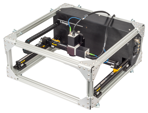
Accessories and Fixturing for Terahertz Gauging & Imaging
Spectroscopy Rail; Collinear Adapter; Lens Options, T-Image Platform Luna’s T-Ray ASR5001 is the first compact pulsed terahertz measurement system that is robust enough to be deployed in an industrial environment and has all of the flexibility provided by Luna’s fiber-coupled sensor heads in a rack mount package. With Luna’s range of accessories and fixturing devices, the T-Ray® 5000 can be configured to fit your specific application. With its exceptionally long high-speed delay, the T-Ray® 5000 is ideally suited for spectroscopic investigations, providing spectral resolution down to 1.5 GHz at 100 Hz. The transmitter (HTS40nm) and receiver (HRS40n1) can be mounted on the T-Ray® ASR5001 spectroscopy rail to perform transmission spectroscopy measurements. A standard mount is provided to hold accessories or standard sample cards. The rail can accommodate lenses up to 150 mm working distance. An iris is provided on the sample holder to block any portions of the beam that may not be going through the sample. Tip-tilt stages provide easy optimization of the beam alignment to ensure maximum bandwidth. Using the T-Ray® 5000 AXA40n1 collinear adapter, transmitter and receiver can be coupled to perform as an integrated collinear reflection transceiver. Alignment pins provide precise positioning. The adapter has two ports for the lens, so it can be assembled as right or left-handed. Reflection measurements are easily acquired because the transmitter and receiver share the same lens. Spatial resolution down to 100 µm has been obtained using this arrangement with a 25.4 mm focal length lens. The transceiver is ideal for reflection tomography. When used with an HTS40nm and an HRS40n1, the assembled collinear transceiver based on ASR5001 or AXA40n1 will provide over 3.5 THz of bandwidth and SNR of 70 dB (ASR5001) or 60 dB (AXA40n1) respectively. The T-Ray® 5000 HTS/HRS Transmitters & Receivers come standard with a 38 mm diameter lens in an adjustable lens tube. In addition to that, Luna offers T-Ray® 5000 lens options ranging from 38.1 mm to 76.2 mm and 152.4 mm in diameter, with focal lengths ranging from 25.4 mm and 76.2 mm to 152.4 mm and 304.8 mm, plus a collimating lens. Here, the “focal length” is the distance from the lens surface to the beam waist. Lens tubes that mount on the transmitter or receiver are also available for 38.1 mm and 76.2 mm lenses. The lenses are manufactured from high-density polyethylene (HDPE) and are manufactured to an aspheric profile for high-quality focusing across a wide range of frequencies. Luna has specifically designed these lenses for use with their fiber-coupled transmitter and receiver sensor heads. When mounted on the front of a transmitter, the lens will provide a collimated or a focused beam. Use relay lenses in conjunction with a collimating lens on the sensor head. The collinear adapter (AXA5001) and the integrated collinear transceiver (HXC50xn) are compatible with 38.1 mm diameter lenses. The T-Ray® 5000 MSL5201 T-Image platform can be positioned for horizontal or vertical scanning. The transmitter and receiver can be configured in transmission or collinear reflection geometry by using the collinear adapter. The MSL5201 can move at speeds up to 150 mm/s and can provide step resolutions below 30 µm. The motors are integrated with the required amplifier and encoder to allow high-quality images to be acquired at speeds up to 1000 pixels/s. The T-Ray® 5000 MSL5201 T-Image platform has an embedded motion controller that is configured by software running on the Terahertz Control Unit. Key Features T-Ray® ASR5001 Spectroscopy Rail: Easy Alignment Without an Optical Table Sample Mounting Fixture With Integrated Iris No Tool Required to Change Lenses Accommodate Various Focal Length Lenses Use to Measure Transmission Spectroscopy Compatible With HTS40nm and HSR40n1 Rail Length: 60 cm Dimensions: 60 x 15.5 x 7.5 cm Weight: 2.0 kg Key Features AXA40n1 Collinear Adapter: Easily Switch to Transceiver Configration Simple Orientation to Target No Tool Required to Change Lenses Expands System Capability Use to Measure Layer Thickness Use to Produce Scanned Images Compatible With HTS40nm and HSR40n1 Variety of Focal Lengths Available Right or Left Handed Operation Polarization Extinction Ratio (PER): >20:1, Horizontal Beam Diameter: 38 mm Available Lens Focal Length: 25 mm, 75 mm, 150 mm, Collimating Lens Mounting Hardware: ¼-20 Threaded Mounting Holes Dimensions: 70 x 64 x 70 mm Weight: 320 g Key Features T-Ray® 5000 Lens Options: Low Loss Simple Alignment No Tool Required for Installation Compatible With Transmitter or Receiver Compatible With Collinear Adapter Lens Diameter: 38.1 mm, 76.1 mm, 152.4 mm Lens Focal Length: 25.4 mm, 76.2 mm, 152.4 mm, 304.8 mm Adjustable Lens Tubes Available for 38.1 mm, 76.1 mm Diameter Lenses Key Features T-Ray® 5000 MSL5201 T-Image Platform: Fiber-coupled to Allow Easy Movement Image Resolution to 100 µm Perfect for Field Work Built to Operate Upright or Prone Easy to Use Imaging Software Available Transmission or Reflection Images Multiple Lens Configurations Available Scan range: 30 cm Minimum Step: <30 µm Focal Lengths: 25 mm, 75 mm, 150 mm Power Supply Voltage Requirements: 110/240 VAC Dimensions: 660 mm x 699 mm x 330 mm Weight: 21.3 kg Applications: Time Domain Spectroscopy; Time Domain Reflection Tomography; Defect Detection; Basis Weight Measurement; System Optimization & Verification; Reaction Kinetics Monitoring; Medical & Biological Research; Nondestructive Materials Inspection; Package Inspection; Semiconductor Wafer Inspection; Remote Threat Detection; Homeland Security
REQUEST PRICING AND AVAILABILITY
- Get your individual quote.
- Technical compatibility review included.
- Volume discounts available.
No obligation. Direct access to our engineering team.
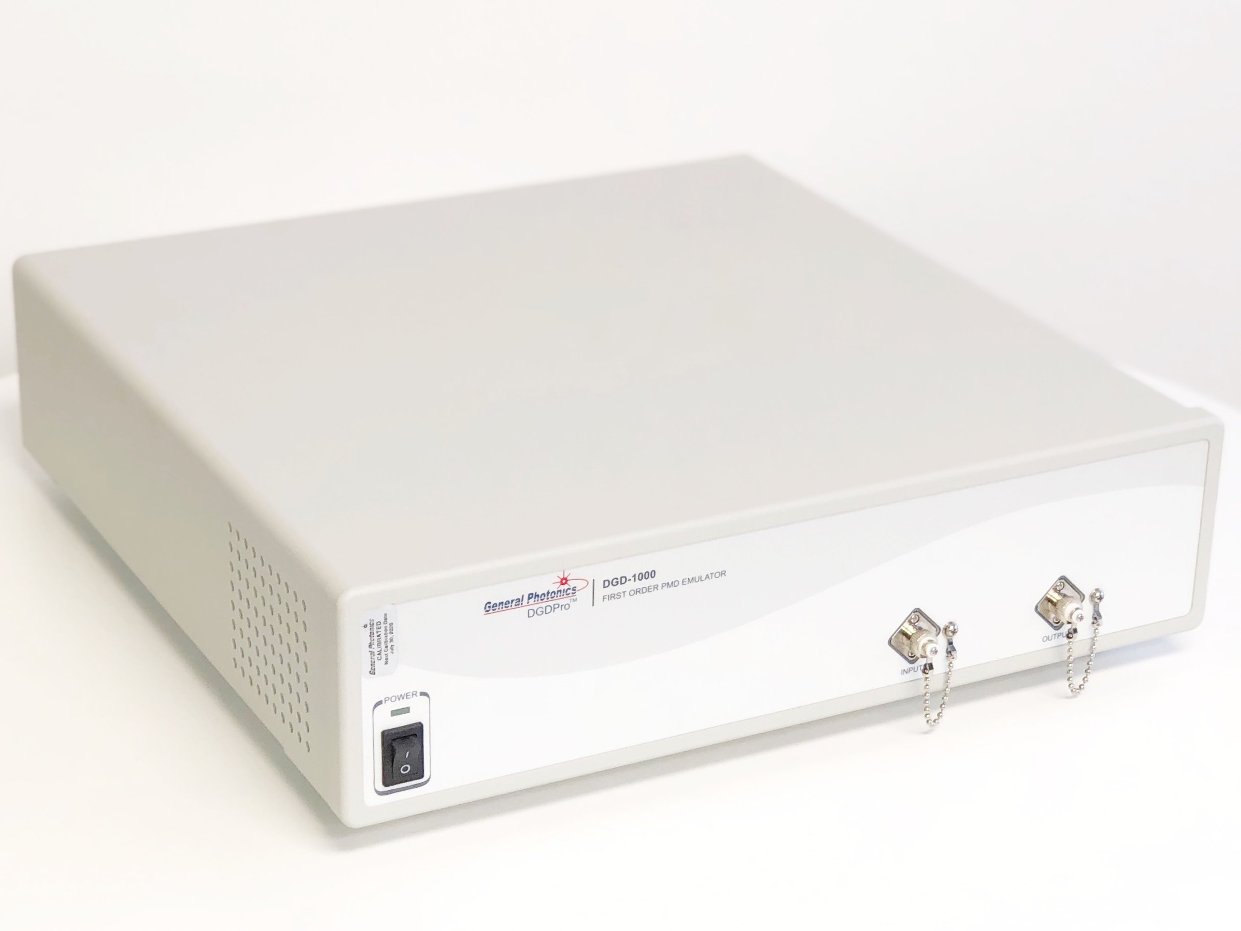
DGD-1000 PMD Source
DGD Range 0-200, 0-44 ps; DGD Resolution 0.2 ps; Single Band C, L, O, Dual Band CL; Max. IL 3.5 dB; Max. PDL 0.3 dB; RL >50 dB Polarization mode dispersion (PMD) can seriously degrade the quality of high-speed fiber-optic data transmission. High-speed transceivers must meet stringent standards for PMD tolerance. General Photonics’ DGD-1000 PMD Source/Emulator accurately and repeatably generates both high and low values of differential group delay (DGD) or first-order PMD. Both the DGD and PDL are very stable over time and wavelength within the performance band. The DGD-1000 PMD source/emulator is available in different versions to accommodate the need for different wavelengths and DGD ranges. Key Features: Generates Differential Group Delay DGD up to 400 ps DGD Range: 0 to 200 ps, 0 to 400 ps DGD Resolution: 0.2 ps DGD Change Rate: Up to 64 ps/s Wavelength Range Single Band: C Band, L Band or O Band Wavelength Range Dual Band: CL Bands Insertion Loss (IL): ≤3.5 dB Very Low Insertion Loss (IL) Variation Over DGD Range: 0.1 dB typ. Very Low Polarization Dependent Loss (PDL) Over DGD Generation Range: 0.3 dB max., 0.1 dB typ. Return Loss: >50 dB Slow SOP Variation: <1 rad/min Small DGD Variation Over Time: <0.1 ps Over 8 Hours Extended Version Can Cover up to 600 ps as Special Order Applications: System PMD Tolerance Testing; 1st Order PMD Performance Simulation
REQUEST PRICING AND AVAILABILITY
- Get your individual quote.
- Technical compatibility review included.
- Volume discounts available.
No obligation. Direct access to our engineering team.
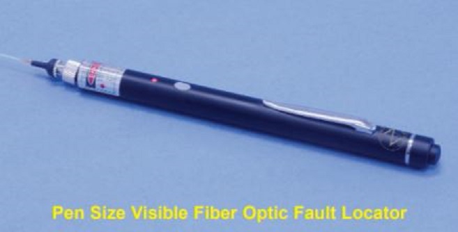
FODL Fault Locators
520 to 660 nm; Optical Power 0.5 to 30 mW; CW to 2 kHz; Connector Type Super/Angled NTT-FC/PC, SC, ST, Universal OZ Optics’ FODL series of visible fiber optic fault locators launches 635 nm visible laser diode light into the fiber. When light encounters a break or sharp bend, it scatters, and the scattered light can be observed emerging from the cable. Fault locators can locate breaks in short patchcords, which an OTDR cannot detect due to its operating dead zone. A fault locator is also much less expensive than an OTDR. However, they are not recommended for use with dark-colored or armored cables. Another use for fault locators is to check connector quality – inside the connector ferrule, poor gluing or dirt may create a micro bend in the fiber producing excess insertion or return losses and maybe resulting in premature failure of the connector. Launching visible light through the fiber, so that it emerges from the connector in question, the distortion appears as a series of rings superimposed on a normal output. Fault locators are available in bench-top, pocket and pen format. Pocket size fault locators can be operated in either CW or pulse modulation mode. Pen size fault locators are CW only. High power versions, available as bench-top units, are also CW only. Key Features: Pen, Pocket and Bench-top Versions Available High Visibility (up to 6 km with a 1 mW, 635 nm Source) Higher Output up to 30 mW, Non-contact Style Power Versions Available Continuous Light or Pulse Modulation Power Supply Alkaline Batteries or AC/DC Adapter Carrying Pouch with Belt Clip for Pocket-size Version 1.25 mm and 2.5 mm ID Universal Connector Receptacles Available Applications: Single Mode and Multi Mode Fiber Testing; Fiber Identifier Applications; Locating Breaks and Bends in Fibers and Connectors; Identifying Fibers and Tracing Optical Signals by Using Modulated Signals; Optimizing Splices
REQUEST PRICING AND AVAILABILITY
- Get your individual quote.
- Technical compatibility review included.
- Volume discounts available.
No obligation. Direct access to our engineering team.
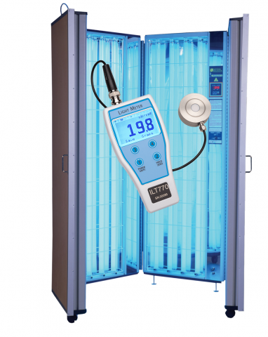
ILT 770 UV Light Meter Series
Wavelength 215-401 nm; ISO/IEC 17025:2017 Accredited; NIST traceable calibrationThe ILT770 is a compact, handheld UV light meter that’s loaded with features. It’s designed for use in a phototherapy booth and comes with built-in data storage, a rechargeable lithium ION battery, and a user-friendly display that shows both numerical and graphical readings. This allows for easy analysis of the system and generation of reports. The units of readout include both Irradiance in W/cm2 and dose in J/cm2, with auto-ranging capabilities (uw/cm2, mW/cm2 uJ/cm2, mJ/cm2, J/cm2 etc).The ILT770 UV light meter is available in five standard configurations:ILT770-UV: 215-350 nmILT770-NB: 249-259 nmILT770-NBUVB311: 275-325 nmILT770-UVA-350: 315-390 nmILT770-UVA-1: 326-401 nmEach package includes an ILT770 light meter, a UV sensor (options include UVC, Narrow band UVC, Narrow band UVB, UVA or UVA-1), a NIST traceable – ISO17025 accredited calibration with certificate, a storage case, a USB cable, PC software for downloading stored readings, and a 1-year warranty. This is a comprehensive solution for your UV measurement needs.Key features: SO/IEC 17025:2017 Accredited, NIST traceable calibration for results you can trust Measures irradiance and doseGraphical display with data analysisAffordableStores readings that can be downloaded to a PC Compact, portable ergonomic designRechargeable battery Create reports with downloaded data Easy-to-use interface Made in the USA BNC connector locks sensor in placeLinear over 4 decades of light levelsApplications: Validation of UV disinfection systems; testing of UVA and narrow-band UVB sources, e.g. for skin treatmentPlease note that International Light products are available from us only in Denmark, Finland, Iceland, Italy, Norway, and Sweden.
REQUEST PRICING AND AVAILABILITY
- Get your individual quote.
- Technical compatibility review included.
- Volume discounts available.
No obligation. Direct access to our engineering team.
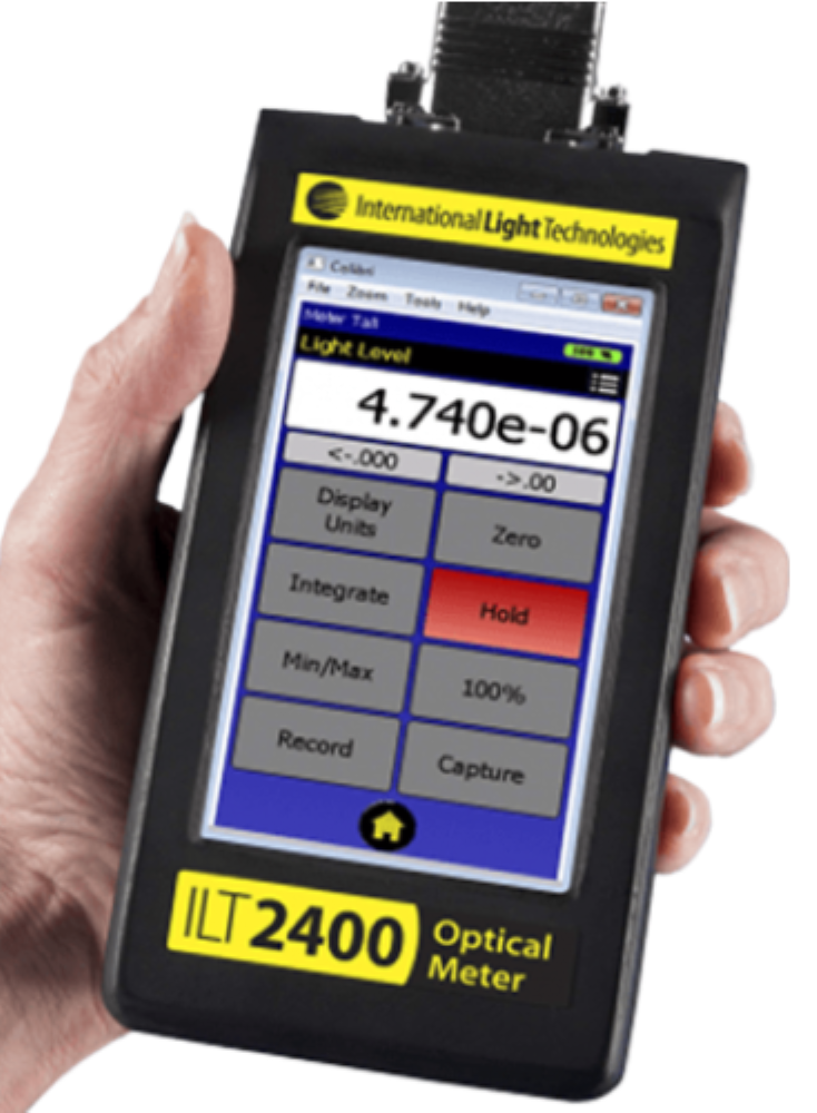
ILT2400 Handheld Light Meter and Optometer Series
Measurement Range: > 10 Decades 100 fA - 1 mA - (1 n/Wcm2 to 10 W/cm2); Datalogging Memory 16,380 total light level readings; Operating Temperature -40 - +85°CThe ILT2400 stands out as the market’s most advanced hand-held light/lux meter and optometer. It comes equipped with ILT’s Accuspan software, which automatically sets the averaging while swiftly measuring over eight decades of light intensities. The built-in software enables customers to capture a peak as brief as 100μS and store up to 16 readings per second. The color display is versatile, functioning in both landscape and portrait modes.ILT, based in Peabody, MA, USA, manufactures the ILT2400 and its software. This allows ILT to quickly configure and customize components to meet the needs of customers and OEMs.The ILT2400 optical measurement systems package includes an ILT2400 device, carrying case, software, and a detector/filter/optic and calibration configured to the customer’s needs. The ILT2400 optical measurement systems enable direct reading in the relevant empirical units, including lux, foot-candles, candela, lumens, watts, W/cm2, cd/m2, foot-lamberts, nits, etc. The ILT2400 and its software are compatible with most computers running Windows 7 and Windows 8.Key features: Research Quality at a Hand-held Price8 Decade Dynamic Range of Optical AnalysisMeter & Sensors with NIST Traceable ISO17025 Accredited CalibrationHand-held, Compact, Ergonomic DesignBrilliant 4.3” Touch Screen Display90° Screen Rotation for Landscape and Portrait ViewingILT’s Accuspan: Auto-ranging with Smart AveragingBuilt-in Rechargeable Battery Lasts Up to 8 HoursBackwards Compatible with ILT1700 SensorsMeasurement Speeds Up to 100 μSecondsIncludes DataLight III comprehensive software package for both Mac and PC Made in the USAApplications: Audience Scanning Laser Safety, General Purpose Light Measurements, Research, Sterilization/UVGI, Solar Measurements, Photoresist/Lithography, Optical Radiation Hazard, Phototherapy, Photo-Degradation, PPF & PPFD Plant Studies, and more.Please note that International Light products are available from us only in Denmark, Finland, Iceland, Italy, Norway, and Sweden.
REQUEST PRICING AND AVAILABILITY
- Get your individual quote.
- Technical compatibility review included.
- Volume discounts available.
No obligation. Direct access to our engineering team.

ILT2500 Light Measurement System
The ILT2500 is a powerful, all-in-one light measurement solution designed for professionals who need precision, flexibility, and ease of use. Whether you're working in the lab, the field, or on the production floor, the ILT2500 delivers high-performance measurements for both steady-state and pulsed light sources. With its modular design, intuitive apps, and accredited calibration, it’s ideal for a wide range of photometric and radiometric tasks.Key FeaturesCombines handheld portability with lab-grade measurement capabilitiesSupports steady-state and pulsed light profiling (including flash and strobe)NIST-traceable and ISO/IEC 17025:2017 accredited calibrationMultiple apps for specialized tasks: Meter, Flash, Beacon, Trend, and moreCompatible with a wide range of sensors, input optics, and integrating spheresUser-friendly interface with portrait and landscape display modesBuilt-in data logging, graphing, and customizable alertsApplications: UV and visible light source testing; LED and laser characterization; Xenon flash and strobe measurement (e.g., NFPA72 compliance); Environmental and workplace light monitoring; Research and laboratory photometry; Quality control in manufacturing and product developmentPlease note that International Light products are available from us only in Denmark, Finland, Iceland, Italy, Norway, and Sweden.
REQUEST PRICING AND AVAILABILITY
- Get your individual quote.
- Technical compatibility review included.
- Volume discounts available.
No obligation. Direct access to our engineering team.
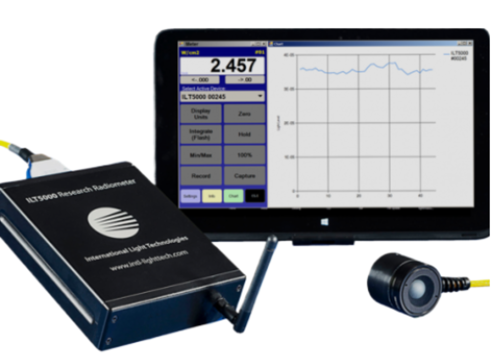
ILT5000 Research Lab Radiometer International Light
Measurement Range 100 fA - 1 mA; Reverse Bias 2 Voltages/Selectable; Operating Temperature -40 - +85 °C; Calibrated Irradiance 0 - 40 °CThe ILT5000 radiometer is the ILT1700 for the 21st Century! Improvements on the industry standard ILT1700 include rapid optical measurements (1-100hz), a broader dynamic range (100fA to 1mA), Datalight III for PC and Mac, plus built-in wireless, data storage, and rechargeable batteries.The ILT5000 is backwards compatible with the ILT1700 sensor configurations, as well as all of ILT's sensor accessories including filters, optics, integrating spheres and ISO/IEC 17025:2017 Accredited/NIST traceable calibrations.ILT manufactures the ILT5000 and DataLight III radiometer in the USA at our Peabody, MA facility which allows us to rapidly customize system components to meet the needs of our customers and OEMs.ILT5000 optical measurement systems typically consist of the ILT5000 light meter, a sensor, filter, optic and calibration to allow direct reading in the appropriate empirical units including lux, foot-candles, candela, lumens, watts, W/cm2, cd/m2, foot-lamberts, nits, etc.Measurement systems: The ILT5000 meter requires a sensor to measure light. Sensors are available to measure from 185 nm out to 40 micron and are supported with a vast array of accessory including bandpass filter, cosine receptors, integrating sphere, and numerous types of calibration.Key Features:Measurement Range: Over 10 Decades 100 fA - 1 mA- (1 n/Wcm2 to 10 W/cm2)Datalogging Memory: Can store 16,380 total light level readings or 8,190 light level with real time stamp(At one reading per minute, this equates to 11.3 days (real time stamp off) or 5.6 days of logging with time stamp on)Built-in Wi-FiOperating Temperature: -40 to 85° C (Calibrated Irradiance: 0-50° C)USB: USB2, Including Power, for Single and Multiple SystemsUSB Current Draw: 500 mA max., 250 mA typicalSize: 1-3/5" H x 5" W x 7" LInput Connector: D-Sub and SMACE Certified: No rf noiseCalibration: NIST Traceable/ISO 170254 - 20 mA outputSample rate up to 100 Hz, programmableAuto-range, Auto-dark, Auto-sample with user control optionsBuilt-in rechargeable battery pack"Set it & Forget it" remote data loggingContinuous multi-system monitoringBackward compatible with the ILT1700 SED detector/filter/opticsLabview compatibleNIST Traceable / ISO/IEC 17025:2017 Accredited calibration and certificateIncludes DataLight III comprehensive software package for both Mac and PCComes with ILT's DataLight III Software includedDataLight is all about supplying fast, reliable light measurement data to you computer for analysis. Our extensive light measurement software package is available for Windows PC, Tablet and MAC computers.DataLight III includes our "set it and forget it" remote internal data storage app., an improved All-in-One meters app for control and transmission of data using a mini USB cable or wireless data transmission, as well as a full API and command line interface for user programming and customization.Applications: Radiometry, Photometry, Reasearch, UVGI- Sterilization, Solar, Photoresist, Optical Radiation Hazard, Phototherapy, Photo-degradation, Plant Growth and morePlease note that International Light products are available from us only in Denmark, Finland, Iceland, Italy, Norway, and Sweden.
REQUEST PRICING AND AVAILABILITY
- Get your individual quote.
- Technical compatibility review included.
- Volume discounts available.
No obligation. Direct access to our engineering team.

ILT750 Bili Light Meter Series
Wavelength 420-520 nm; Band Irradiance Range .08 to 8000 µW/cm2/nm; Irradiance Range 3 to 300,000 µW/cm2; Current Range 1 nA to 1.65 uAThe ILT750 Bili Light Meter is available in two configurations:ILT750 Bili Light Meter – 470 nm ILT750 Bili454 Light Meter – 454 nm, direct substitute for the Ohmeda Light Meter The ILT750 Bili Light Meter is a comprehensive solution for measuring light in neonatal jaundice treatment systems. This bilirubin light meter eliminates the need for manual recording and calculation of multiple measurements to obtain your irradiance value. Simply move the ILT750 detector over the blanket or under the light source and let the meter calculate for you.Key features:Dual units with a wide sensitivity range: from .08 to 8000 µW/cm2/nm, and 3.0 to 300,000 µW/cm2User-friendly device3-digit display resolutionPeak response at 470 nm, aligning with the bilirubin action spectrumCalibration that is ISO/IEC 17025:2017 Accredited and NIST TraceableSensor corrected for cosine for accurate spatial responseMeasures Band Irradiance (µW/cm2/nm) or Irradiance (W/cm2)Compatible with traditional and LED sourcesSuitable for bili blankets, pads, or overhead lampsHousing that is easy to cleanCompact and ergonomic design that is easy to holdPowered by AA batteriesMade in the USA The ILT750-BILI454 Light Meter serves as a direct substitute for the Ohmeda light meter, designed to test both traditional and LED blue light sources from GE, which are used in the treatment of neonatal jaundice. The advanced capabilities of the ILT model remove the need for manual calculations or note-taking. Simply move the detector across the blanket or beneath the light source, and the meter will handle the calculations for you.After rigorous design and testing, the ILT750-BILI454 meter can read within a few percentage points of the discontinued Ohmeda Biliblanket II Blue light meter. This meter is versatile and can be used not only on the blanket but also on all GE lighting systems, including:GE Giraffe SystemsGE Lullaby SystemsGE BiliSoft SystemsTraditional GE Blue light systemsKey features:Measures within a few percentages of the discontinued Ohmeda meterFeatures a large, easy-to-read OLED displayCalibrated at 454 nm using a GE LED light sourceCan verify and average irradiance values across the entire treatment area in less than a minuteCalibration is ISO/IEC 17025:2017 Accredited and NIST TraceableAllows selection of units (µW/cm2/nm or W/cm2)Designed with an easy-to-hold, lightweight, and ergonomic design that’s easy to cleanCustom filter matching is designed into the deviceMade in the USAApplications: testing of GE traditional and LED blue light sources for treatment of infant jaundicePlease note that International Light products are available from us only in Denmark, Finland, Iceland, Italy, Norway, and Sweden.
REQUEST PRICING AND AVAILABILITY
- Get your individual quote.
- Technical compatibility review included.
- Volume discounts available.
No obligation. Direct access to our engineering team.
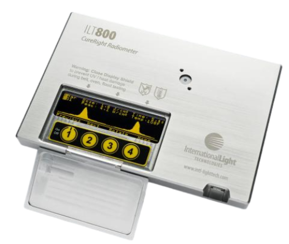
ILT800 CureRight Radiometer Series
Wavelength 215-475 nm; Range 4.5 decade (mW/cm2 to 40W/cm2); Temperature 0-75 °C (internal case temperature)The ILT800 CureRight is a UV curing radiometer that is packed with features, offering unparalleled flexibility and capabilities not found in any other system. Its adaptability enables the device to measure lights used for UV curing and a variety of other applications such as sterilization/disinfection, lithography, and more. The system is designed with the diverse needs of its users in mind and can be tailored to fit your specific environment.The ILT800 CureRight series validates and measures all kinds of UV curing methods and sources, including conveyor, belt, oven, flood, area, spot, fiber optic, collimated beam, side cure, 180° curing, 3D printing, pulsed and traditional UV lamps, and UV/VIS LEDs & light sources.The ILT CureRight is available in five standard configurations:ILT800-UVA: 315 - 390 nmILT800-BAV: 275 - 475 nmILT800-UV: 250 - 400 nmILT800-CUV: 215 - 350 nmILT800-UVF (UV LED): 360 - 400 nm Flat, (275 - 450 nm)Contact us for OEM / Custom FiltrationThe ILT800 CureRight UV radiometer system surpasses competitors with features like standard profiling and programmable settings such as measurement modes (auto/manual/live), minimum light level threshold, and lamp-to-lamp measurement interval (delay). The system also boasts a unique user interface that places the input sensor and optic, device controls, and the readout display all on one side, facilitating simultaneous measurement, monitoring, and analysis of measurement data.The ILT800 UV radiometer allows users to track their curing processes over time by allowing them to store, download, and view both current and all previously saved readings on the device’s integrated OLED display. This built-in data storage and review feature enables users to quickly identify changes that have occurred over time. It also helps users to easily spot potential issues in their systems such as dirty lamps and reflectors, lamp/reflector misalignment, declining lamp output, failed lamps, and power supply problems, among others. Additional benefits include the ability to download the results to a computer for more detailed analysis. With ILT’s proprietary DataLight CureRight software interface, users can download and view their data, as well as generate spreadsheets and reports using their own analysis tools.To further enhance the data storage and capabilities, ILT introduced an advanced sorting feature called Device ID, a feature not found in any other UV curing light meter. Device ID allows users to program up to 20 unique system/light source name tags. Device ID enables users to view and export all saved data for each curing station or light source into separate files, clearly identified with the Device ID. It’s like having the functionality of multiple meters in a single device.The ILT800’s spectral filtration was designed to match the photoinitiators’ response to UV light, which is directly related to its absorption and is highly wavelength selective. Most lamps emit broadband UV/VIS/IR, and the lamp’s output may not change evenly across all wavelengths. The ILT800 filters were designed to monitor changes in output in the areas that affect absorption, and consequently, the effectiveness of the curing. Whether you’re using a low-output fluorescent source for sterilization, high-intensity mercury or xenon lamps for curing, or narrow-band LEDs for photolithography, there’s a version of the ILT800 tailored for your needs.Filtration options covering UVC to UV-VISFiltration to ensure a process matchMeasures only the light that effects the cureApplications: low-output fluorescent sources for sterilization, high-intensity mercury or xenon lamps for curing, narrow-band LEDs for photolithographyPlease note that International Light products are available from us only in Denmark, Finland, Iceland, Italy, Norway, and Sweden.
REQUEST PRICING AND AVAILABILITY
- Get your individual quote.
- Technical compatibility review included.
- Volume discounts available.
No obligation. Direct access to our engineering team.
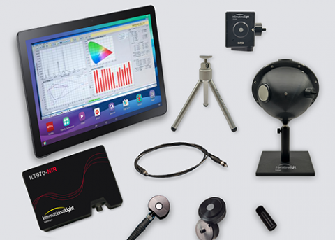
ILT970 Spectroradiometric Measurement Systems
The VNIR Spectroradiometric Measurement Systems from ILT are designed for optimal performance in the visible (VIS) and near-infrared (NIR) spectral ranges, with calibration spanning from 380 nm to 1000 nm. Users can select from seven configurations tailored for measuring spectral irradiance (W/cm²-nm), spectral radiance (W/cm²-sr-nm), and spectral flux (W/nm).Each system includes a VNIR spectrometer with an optical fiber, a measurement head for either spectral irradiance or flux, a stand, SpectrILight III control software with DLLs, and a convenient carrying/storage case.These systems are thoroughly characterized and calibrated for accurate spectroradiometric performance, adhering to ISO 17025-certified procedures. Key features: Broad Spectral RangeVersatile Measurement OptioknsComplete System PackageISO 17025-Certified CalibrationGlobal Recalibration SupportMulti-Parameter Light AnalysisApplications: Color management, light source characterization, inspection, validation, production testing, and R&D.Please note that International Light products are available from us only in Denmark, Finland, Iceland, Italy, Norway, and Sweden.
REQUEST PRICING AND AVAILABILITY
- Get your individual quote.
- Technical compatibility review included.
- Volume discounts available.
No obligation. Direct access to our engineering team.

iOSNRG-1000-TUN Benchtop Intelligent Optical Signal-to-Noise Ratio Generator
OSNR Range 5-38 dB; 1529-1561.5 nm; Min. Optical Input Power -10 dBm, Min. Optical Output Power +8 dBm; Channel Spacing 50-400 GHz OZ Optics' iOSNRG-1000-TUN intelligent optical signal-to-noise ratio generator (iOSNRG) has been designed to allow users to inject a programmable level of noise into an optical signal, creating a precisely defined signal-to-noise ratio. All iOSNRG settings can be controlled automatically with the user-friendly touch panel or computer interface. With a built-in bandwidth-adjustable tunable filter, the wavelength can be selected to be any channel within the ITU 50G Grid or any other ITU Grid. The output power level is user programmable, making the iOSNRG-1000-TUN an ideal instrument for doing OSNR measurements in data communication systems. The instrument comes with GPIB, USB, and Ethernet interfaces, allowing it to be controlled by a computer, for automated testing of systems or devices. Key Features: User Selectable Optical Signal-to-noise Ratio (OSNR) and Power Level Built-in Tunable Filter with Adjustable Bandwidth Stand-alone Device with Touchscreen Control for Local Operation GPIB, USB, and Ethernet Interfaces for Computer Control Optical Port for Connecting External Optical Spectrum Analyzer Provision for External Filter Direct Output from Tunable Filter or with EDFA Amplification Supports 50G/100G/200G/400G Applications OSNR Range: 5 dB to 38 dB OSNR Setting Accuracy: ±0.5 dB Optical Input Power: >-10 dBm Optical Output Power:: ≥+8 (dBm) Wavelength: 1529 nm to 1561.5 nm Channel Spacing: 50/100/200/400 GHz Fiber Core/Cladding: 9/125 μm Supply Voltage: 110–220 VAC, 47-63 Hz Max. Electrical Power: 80 W Dimensions1: 390x344x86 mm Weight: 7.5 kg Applications: Fiber Optic Network Testing; Bit Error Rate (BER )Testing; Eye Diagram Quality Testing; DWDM Network Testing; Submarine Network Testing
REQUEST PRICING AND AVAILABILITY
- Get your individual quote.
- Technical compatibility review included.
- Volume discounts available.
No obligation. Direct access to our engineering team.
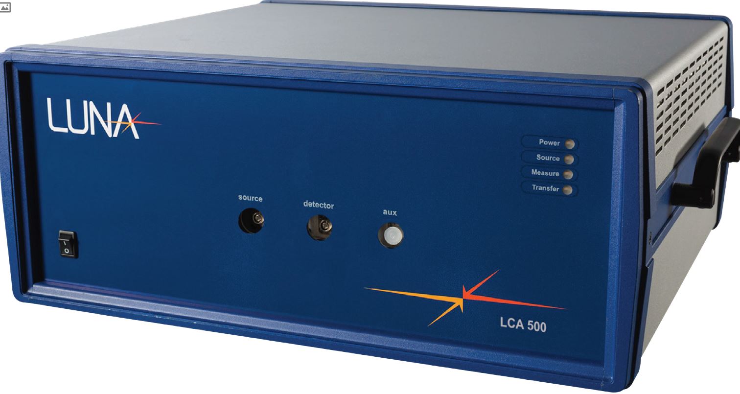
LCA 500 Lightwave Component Analyzers
1270-1610 nm; Wavelength Resolution 1.6 pm; Loss Measurement Dynamic Range 60, 80 dB; Loss Measurement Resolution ±0.002, ±0.05 dB; Laser Sweep Rate 70 nm/s; Measurement Time 12, 55 s; Maximum Device Length 75, 150 m Luna’s LCA 500 lightwave component analyzers are fast and accurate systems that are ideal for production test and quality control. The LCA 500 series provides the high throughput and connectivity needed for the manufacturing floor while delivering the extremely high resolution and sensitivity that is critical when testing and validating modern photonic devices and network subsystems. The LCA 500 lightwave component analyzers provide single-scan measurements for testing a wide range of passive components from couplers to Optical Fibers and everything in between (Fiber Bragg Gratings, arrayed waveguide gratings, free-space filters, tunable devices, amplifiers, etc.). Key Features: Single Scan Measurement of Insertion Loss (IL), Return Loss (RL) and Polarization Dependent Loss (PDL) High Resolution: 1.6 pm High Sensitivity: 80 dB Dynamic Range Integrated Tunable Light Source – No External Tunable Laser Needed Measure in Transmission or Reflection Compatible With C and L Band (LCA 500) or O Band (LCA 513) Complete Full-band Measurement Scan in Less Than 3 s User-friendly Interface Wavelength Range: 1270 to 1610 nm Wavelength Resolution: 1.6 pm Loss Measurement Dynamic Range: 60, 80 dB Loss Measurement Resolution: ±0.002, ±0.05 dB Laser Sweep Rate: 70 nm/s, 1 Hz Measurement Time: 12, 55 s Maximum Device Length: 75 m (Reflection), 150 m (Transmission) Applications: Testing of Passive Components like DWDMs, AWGs, Filters, Switches, Waveguide Gratings, Modulators, Couplers, etc.; High-resolution Measurements for Planar Light Circuits (PLCs) and Silicon Photonic Devices; Manufacturing Test and Quality Control; Flexible Tunable Laser Source splitters
REQUEST PRICING AND AVAILABILITY
- Get your individual quote.
- Technical compatibility review included.
- Volume discounts available.
No obligation. Direct access to our engineering team.
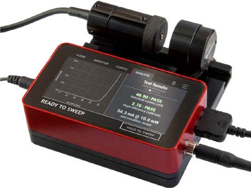
LDA-100 Laser Diode Analyzer
Laser Diode Current 0-500 mA; LD Compliance Voltage 0.0-8.0 V; TEC Current 0-1 A; TEC Voltage Range ±8.00 V; Photodiode Current 0-3600 μA; Setpoint Resolution 0.1 mA; Setpoint Accuracy ±0.05% OZ Optics’ LDA-100 low cost, compact and standalone laser diode analyzer provides quick and versatile laser diode characterization and parametric analysis. The unit features a high-resolution LIV (light, current, voltage) measurement system, providing all main laser diode parameters including threshold current and slope efficiency. The setup and measurement takes only a few seconds. The measured parameters are displayed on a color touch screen, and the data can be downloaded to any host computer for further processing and analysis through a built-in USB interface. The unit features a built-in smart driver that will automatically detect the laser diode pinout. The user can select to operate the laser diode under test in either auto-current or auto-power control modes. The integrated TEC controller maintains your diode at its operating temperature, ensuring accurate and repeatable measurements. The smart laser diode analyzer comes with multiple features for safe and accurate measurements. These features include current limit protection, automatic pinout detection, sensor range checks and manager passcode level to prevent any accidental changes of the preset settings that could otherwise harm the laser diode under test, or invalidate the results. External interlocks can be connected to disable the laser diode in response to safety concern situations. Each unit is provided as a set that includes all required accessories for direct plug-and-play operation. The kit includes a calibrated optical power meter head and a thermally controlled laser diode holder for 5.6 mm package laser diodes (holders for 3.8 mm and 9 mm packages are offered separately). A simple sliding mechanism allows easy laser diode replacement. Special laser diode adapters can be customized upon request for any laser diode package. Key Features: Integrated Temperature Controller Compact Plug-and-Play Laser Diode Analyzer Fast and Accurate LIV (Light, Current, Voltage) Curve Generation With 0.1 mA Resolution Setpoint Resolution: 0.1 mA Setpoint Accuracy: ±0.05% Laser Diode Compliance Voltage: 0.0 V to 8.0 V Laser Diode Drive Current up to 500 mA Photodiode Current Range: 0 μA to 3600 μA Photodiode Current Resolution: 0.1 μA 15-bit Power Resolution 3 W Output TEC Temperature Controller Max. TEC Current: 1 A TEC Voltage Range: ±8.00 V Temperature Control Range: +10°C to +50°C Password Protection, Hardware Interlock and Overcurrent Shut-off Circuitry for Safety Built-in Smart Driver for Diode Pinout Auto Detection and Temperature Control Touchscreen Control and Accompanying Windows Software Operating Rel. Humidity: <85%, Non-condensing Dimensions Analyzer: 110 x 63 x 30 mm Dimensions Analyzer + Accessories: 110 x 115 x 45 mm Weight Analyzer: 300 g Weight Analyzer + Accessories: 1000 g Applications: Laser Diode Characterization; Laser Diode Quality Control; Laser Source Calibration
REQUEST PRICING AND AVAILABILITY
- Get your individual quote.
- Technical compatibility review included.
- Volume discounts available.
No obligation. Direct access to our engineering team.
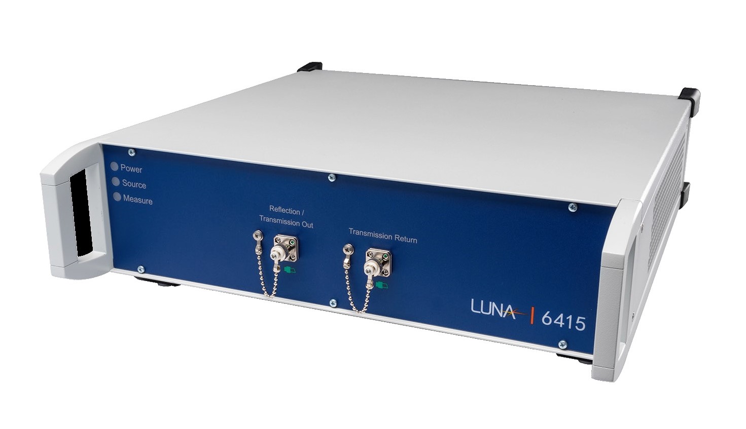
Luna 6415 Lightwave Component Analyzer
OFDR Technology; Spatial Resolution 20 µm; Max. Device Length 20, 40 m; Center Wavelength 1546.69 nm; Wavelength Range 40 nm; Dynamic Range 15, 70 dB The Luna 6415 lightwave component analyzer is a fast and simple-to-use analyzer for passive optical components and modules, extending Luna’s industry-leading optical frequency domain reflectometry (OFDR) platform to manufacturing test and quality control applications. Unlike traditional passive component testers, Luna 6415 measures and analyzes the insertion loss (IL) and return loss (RL) distribution as well as length with a single instrument, working in either reflection or transmission. The Luna 6415 lightwave component analyzer utilizes optical frequency domain reflectometry (OFDR) technology to measure backscattered or transmitted light as a function of distance. The system features extremely high sensitivity, 20 μm spatial sampling resolution and very fast scanning for high test throughput, making it an ideal testing tool for photonic integrated circuits (PICs) and silicon photonics. By integrating both reflection and transmission measurements, Luna 6415 reduces the cost and complexity of test while increasing throughput and provides more complete test coverage of your component. The Luna 6415 lightwave component analyzer further simplifies your manufacturing test with an integrated tunable laser source , automated IL and RL calculations, self-calibration and very high scanning speeds for greater test throughput. Key Features: Return Loss (RL) and Insertion Loss (IL) Analysis Trace Distributed Return Loss (RL) Over Length of Optical Path – Easily Measure Waveguide Scattering Spectral Analysis of Return Loss (RL) and Insertion Loss (IL) Detect and Precisely Locate Reflective Events and Measure Path Length Speed, Resolution and Accuracy for Optimizing Production Test High Spatial Sampling Resolution: 20 μm Measurement Range: 20 m Scan/Acquisition Rate: 6 Hz Maximum Device Length: 20 m (Reflection), 40 m (Transmission) Wavelength Range: 40 nm Center Wavelength: 1546.69 nm Maximum Optical Power: 5 mW Dynamic Range: 70 dB (RL Measurement), 15, 70 dB (IL Measurement, Reflection / Transmission Mode) Return Loss Measurement Sensitivity: -135 dB Measurement Resolution: ±0.1 dB Applications: Spatial RL Testing; Automated Insertion Loss (IL) Test and Analysis; Skew Measurement With Sub-picosecond Resolution; PLCs, Waveguide Devices, AWGs, ROADMs, etc.; Couplers, Switches, Beamsplitters
REQUEST PRICING AND AVAILABILITY
- Get your individual quote.
- Technical compatibility review included.
- Volume discounts available.
No obligation. Direct access to our engineering team.

LWA 7601-C Lightwave Analyzer C Band
The LWA 7601-C Lightwave Analyzer C Band from Luna is a high-performance optical test and measurement instrument designed for the characterization of modern optical components, photonic integrated circuits (PICs), silicon photonics devices, and fiber optic networks. Utilizing advanced Optical Frequency Domain Reflectometry (OFDR) technology, the LWA 7601-C measures backscattered and transmitted light as a function of distance, time, or wavelength, delivering unparalleled insight into optical performance.Engineers and manufacturers face increasing demands for accuracy, speed, and efficiency when testing optical devices. The LWA 7601-C addresses these challenges by combining return loss (RL), insertion loss (IL), and length measurements within a single instrument, significantly reducing test complexity while improving throughput. Its exceptional sensitivity and 20 μm sampling resolution make it particularly valuable for applications where precise fault location and detailed optical analysis are critical.Whether deployed in research laboratories, production environments, or network validation applications, the LWA 7601-C provides a comprehensive solution for analyzing optical components in both reflection and transmission modes. With a measurement range of up to 500 meters for path length analysis and high-speed acquisition rates of up to 12 Hz, users can quickly identify issues, optimize device performance, and streamline testing workflows.Key featuresThe LWA 7601-C offers a powerful feature set that enables accurate and efficient testing of optical components and assemblies.Return Loss (RL) and Insertion Loss (IL) AnalysisSimultaneously evaluate critical optical performance parameters to gain a complete understanding of component quality and behavior.Reflection and Transmission MeasurementsAnalyze optical devices in both reflection and transmission modes with a single instrument, eliminating the need for multiple test systems. Distributed RL MeasurementTrace return loss along the entire optical path, making it possible to identify reflections and losses at specific locations within a device or network.Spectral Analysis CapabilitiesPerform detailed spectral analysis of insertion loss and return loss characteristics to better understand wavelength-dependent performance.Precise Event Location and Length MeasurementDetect, isolate, and accurately locate reflective events while measuring optical path length up to 500 meters, supporting rapid troubleshooting and validation.High Resolution and SensitivityA sampling resolution of 20 μm enables detailed analysis of optical structures and facilitates the detection of even minor performance variations.Fast Acquisition SpeedWith a measurement rate of up to 12 Hz, the analyzer supports high-throughput testing and production optimization.Production-Ready DesignAn optional 19-inch rack-mount version allows seamless integration into automated test benches and manufacturing environments.These capabilities help organizations reduce testing costs, improve repeatability, and increase productivity across research, development, and manufacturing operations.ApplicationsThe LWA 7601-C is designed to support a broad range of optical testing applications across telecommunications, datacom, silicon photonics, and advanced photonics manufacturing.Spatial Return Loss TestingThe instrument makes it possible to identify and quantify reflections throughout an optical path, allowing engineers to locate defects, connector issues, and component mismatches with exceptional precision.Automated Insertion Loss AnalysisManufacturers can automate insertion loss measurements and analysis processes, improving consistency while reducing manual testing effort and overall production time.High-Precision Skew MeasurementsThe LWA 7601-C supports skew measurements with sub-picosecond resolution, making it an excellent choice for applications requiring precise timing and path matching.Photonic Integrated Circuit TestingThe analyzer is ideally suited for testing advanced photonic devices, including:Photonic Integrated Circuits (PICs)Waveguide devicesPlanar Lightwave Circuits (PLCs)Arrayed Waveguide Gratings (AWGs)Reconfigurable Optical Add-Drop Multiplexers (ROADMs)Its high resolution enables detailed characterization of complex photonic structures and integrated optical systems. Fiber Optic Networks and CablesThe extended measurement range and distributed analysis capabilities make the instrument highly effective for validating fiber networks, cable assemblies, and optical links. Users can rapidly identify losses, reflections, and length-related issues throughout the system.Optical Components and SubassembliesThe LWA 7601-C is also widely used for testing passive optical components such as filters, couplers, switches, beam splitters, fiber Bragg gratings (FBGs), and specialty fiber assemblies, ensuring they meet performance specifications before deployment.What’s next?As photonic technologies continue to advance, the need for faster, more accurate, and more comprehensive optical testing solutions becomes increasingly important. The LWA 7601-C Lightwave Analyzer C Band provides the precision, speed, and versatility required to support next-generation optical component development and production. By combining return loss, insertion loss, spectral analysis, and length measurement capabilities into a single platform, it simplifies testing workflows while delivering highly accurate results.Whether you are developing cutting-edge photonic integrated circuits, optimizing manufacturing processes, or troubleshooting complex fiber optic networks, the LWA 7601-C offers a reliable and scalable solution for achieving superior optical performance. With its advanced OFDR technology, high-resolution measurements, and production-ready design, it is an investment that can help accelerate innovation while maintaining the highest standards of quality and efficiency.
REQUEST PRICING AND AVAILABILITY
- Get your individual quote.
- Technical compatibility review included.
- Volume discounts available.
No obligation. Direct access to our engineering team.
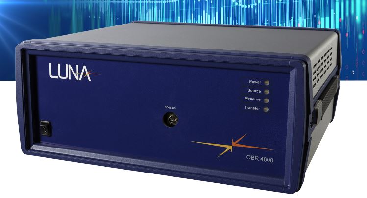
OBR 4600 Optical Backscatter Reflectometers
Zero Dead Zone; 1270-1610 nm; Resolution 10-250 µm; Scan Time 0.4-16 s; Max. Device Length 30-2,000 m; Dynamic Range 60, 80 dB; Backscatter-level Sensitivity -130 dB OBR 4600 optical backscatter reflectometers are part of Luna’s award-winning OBR Optical Backscatter Reflectometer product line. Designed for component testing, short run network testing and troubleshooting, the OBR 4600 reflectometers enable ultra-high resolution reflectometry with backscatter level sensitivity. The OBR 4600 reflectometers feature spatial resolution as fine as 10 µm, no dead zone and an extremely low noise floor. The OBR 4600 comes with an extensive range of options including a strain and temperature sensing package with maximum sensor lengths up to 2 km. To increase the functionality of their OBR 4600 optical backscatter reflectometer, users can add the following options: Spot Scan Option: Allows the user to narrow the scan range to 1 to 2 m area within the network under test. This reduces the time required to scan and also allows the user to focus exclusively on the area of interest. Hard Shell Carrying Case Option: The OBR 4600 can be provided with a hard shell carrying case for applications that require portability or exposure to more rugged environments. 2 km Sensing Length Option: The OBR 4600 range can be extended up to 2 km with a 3 mm spatial resolution and no dead zone. Software Development Kit Option: A selection of DLL files can be provided to allow users to customize their own test equipment user interface with the OBR 4600 operation. Lightpath Analysis Software Option: Allows the user to program a go/no go check based on a pre-selected characterization of a component or network. This option is ideal for testing and can reduce a complicated analysis to a simple pass/fail end of line production test. Distributed Temperature and Strain Sensing Package: This option allows the user to make strain or temperature measurements using sensors made with standard unaltered fiber optic cable that does not require fiber bragg gratings. The distributed sensing option can provide sub-cm spatial resolution with sensors up to 2 km. Key Features: “Zero Dead Zone” Reflectometers Measure Insertion Loss (IL), Return Loss (RL), Distributed Loss, Distance, Polarization States, Phase Derivative and Group Delay Easily Locate, Identify and Troubleshoot Macro-bends, Splices, Connectors and Breaks Dual Display With Intuitive User Interface Allows to Simultaneously Determine Fault Location and Fault Magnitude and Perform Fault or Component Characterization Highlight Selected Sections of the Scan and Perform an Analysis in the Frequency Domain User-selectable Scanning Wavelength Range and Centerpoint Fast Scanning: Measure 30 m with 10 μm Sampling Resolution in <7 s Continuous High-speed Scanning: 1 m Segments at up to 3 Hz Optional Spot Scanning Feature Extended Range Option Provides 2 km Range With no Dead Zone Wavelength Range: 1270 to 1610 nm Maximum Wavelength Resolution: 0.02 pm Maximum Device Length: 30 to 2,000 m Sampling Resolution: 10 to 250 µm Scan Time: 0.4 to 16 s Measurement Rate in Spot Scan Mode: 0.15 to 3.7 Hz Dynamic Range: 60, 80 dB Backscatter-level Sensitivity: -130 dB High-resolution C and L Band (OBR 4600) or O Band (OBR 4613) Capability Applications: Easily Locate, Identify and Troubleshoot Macro-bends, Splices, Connectors and Breaks; Locate Insertion Loss (IL) Points at Every Point in the Network or Assembly – Eliminate Cutbacks; Test and Troubleshoot Short-run Networks (up to 2 km); Unprecedented Visibility into Miniaturized Components
REQUEST PRICING AND AVAILABILITY
- Get your individual quote.
- Technical compatibility review included.
- Volume discounts available.
No obligation. Direct access to our engineering team.
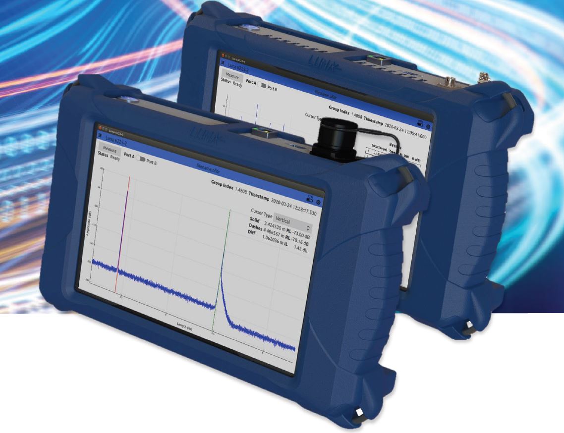
OBR 6200 Optical Backscatter Reflectometers
Portable & Rugged; 1270-1610 nm; Resolution 80-200 µm; Measurement Time 10 s; Measurement Length Modes 10,50,100 m; Dynamic Range 15 (IL), 70 (RL) dB; RL Measurement Sensitivity -129 dB Luna’s OBR 6200 series of optical backscatter reflectometers are portable and rugged ultra-high resolution reflectometers with backscatter-level sensitivity for testing short networks deployed in aerospace, naval, data center and industrial applications. Troubleshoot fiber assemblies in the field to easily locate optical loss events with sub-millimeter resolution. Learn more about highest-resolution OTDR measurements available in the downloadable data sheet. The OBR 6200 series utilizes optical frequency domain reflectometry (OFDR) technology to measure distributed return loss (RL) and insertion loss (IL) with high precision and dynamic range. The systems easily locate optical loss events with sub-millimeter spatial resolution. OBR 6200 optical backscatter reflectometers are rugged battery-powered integrated systems with an intuitive touchscreen user interface, making them ideal for field maintenance applications. The user interface includes screen modes for interactive RL and IL measurement as well as automatic event detection. Key Features: Fully Portable and Rugged Optical Backscatter Reflectometers Track and Analyze Return Loss (RL) and Insertion Loss (IL) Versus Length Spatial Sampling Resolution: Down to 80 μm Detect and Precisely Locate Reflective Events Measure Optical Path Length With High Precision Automatic Event Detection One or Two Optical Channels Available With IP65 and MIL-STD Certifications Measurement Length Modes: 10, 50, 100 m Sampling Resolution: 80 to 200 µm Length Measurement Accuracy: <1 to <4 mm Wavelength Scan Range: 4 to 10 nm Center Wavelength: 1546.7 nm Measurement Time: 10 s Dynamic Range: 70 dB (RL Measurement), 15 dB (IL Measurement) Return Loss Measurement Sensitivity: -129 dB Measurement Resolution: ±0.1 dB Applications: Troubleshoot Fiber Assemblies in the Field; Precisely Locate Insertion Loss (IL) Sites, High-RL (Return Loss) Connections, Fiber Breaks, etc.; Maintain Avionics, Aerospace, Naval and Industrial Networks; Verify Fiber Lengths of Data Center Interconnects; Troubleshoot Fiber Optic Sensing Systems
REQUEST PRICING AND AVAILABILITY
- Get your individual quote.
- Technical compatibility review included.
- Volume discounts available.
No obligation. Direct access to our engineering team.

OCA-1000 Optical Component Analyzer
1260-1620 nm; 8-40 Channels; PDL Measurement Range 0-20 dB; PDL Resolution 0.01 dB; IL Measurement Range 0-60 dB; IL Resolution 0.002 dB; Optical Power Range -60-8 dBm; Optical Power Accuracy ±0.5 dB Lunas’ OCA-1000 is a multi-channel optical component analyzer that simultaneously measures insertion loss (IL), polarization dependent loss (PDL), and optical power (P) on multiple optical paths. The measurement is based on the Mueller Matrix method, which offers fast characterization of wavelength dependent optical parameters that are critical in today’s optical communication systems.The OCA-1000 base model can have up to eight channels. Custom 8- or 16-channel expansion units can be added to increase the system capacity to up to 40 channels. The instrument comes with a control program with built-in functions to display measured power, IL, and PDL vs. wavelength or to monitor the time variation of power/IL for all channels simultaneously to determine their stability. For AWG characterization, the data analysis software also calculates passband center wavelength, bandwidth, and flatness as well as inter-channel crosstalk (from adjacent and nonadjacent channels).The OCA-1000 optical component analyzer is an ideal solution for easy, accurate characterization of components and modules with multiple outputs, including DWDMs, ROADMs, AWGs and PLCs. It can be used with various tunable lasers , such as those from Keysight or Santec. This flexibility makes full use of existing laser resources and reduces the cost of making such measurements. Its rapid measurement reduces the time required to characterize devices with large numbers of ports, enabling higher production throughput.Key Features:Wide Wavelength Range: 1260 to 1360 nm (O-Band), 1480 to 1620 nm (C- & L-Bands)Number of Channels: 8 to 40PDL Measurement Range: 0 to 20 dBHigh Polarization Dependent Loss (PDL) Accuracy: ±(0.02 + 2% of PDL) dB @PDL<10dB, ±(0.02 + 5% of PDL) dB @10<PDL<20dBPDL Resolution: 0.01 dBInsertion Loss (IL) Measurement Range: 0 to 55 dB, 0 to 60 dBIL Resolution: 0.002 dBOptical Power Range: -60 to 8 dBmOptical Power Accuracy: ±0.5 dBHigh Channel-to-channel UniformityUser-friendly Control SoftwareIntegration Time of Power Meter: 0.5 to 1,000 msDimensions: 19”-Rack-Mountable Enclosure, 1 U, 305 mm DepthApplications: PDL or IL vs. Wavelength Measurement; IL or Power vs. Time Measurement; DWDM Component Passband Characterization: Center Frequency, BW, Ripple, Noise Floor; Fiber Optic Component Characterization; Network Component Characterization (e.g. DWDM, ROADM); Planar Lightwave Circuits (PLC); Photonic Integrated Circuits (PIC)
REQUEST PRICING AND AVAILABILITY
- Get your individual quote.
- Technical compatibility review included.
- Volume discounts available.
No obligation. Direct access to our engineering team.

OCDR-1000 Optical Coherence Domain Reflectometer
1310, 1550 nm; Dynamic Range >80 dB; Scan Range 600 mm; Spatial Resolution 10-25 µm; RL Range 10-90 dB; Sweep Speed 20 mm/sLunas’ OCDR-1000 is an optical coherence domain reflectometer designed to obtain space-resolved reflection information inside a fiber optical component, such as a photonic integrated circuit (PIC), for diagnosing quality or design issues. It is based on a polarization optimized white light interferometer proprietary to General Photonics.The OCDR-1000 optical coherence domain reflectometer performs the functions of the discontinued Agilent 8504B Reflectometer – and more – but with better polarization management, spatial resolution and accuracy; larger scan range and dynamic range; and smaller size and weight.The OCR-1000 is a low-cost alternative to OFDR technology, with a much higher dynamic range that avoids the masking of small reflection peaks by the large reflections typical of the input surface of an optical device.The OCDR-1000 optical coherence domain reflectometer can measure devices with a length of up to 600 mm. A set of length-matching delay modules is available to match the pigtail lengths of the devices to be measured and place the measurement span in the region of interest. With a reflection dynamic range of over 80 dB and a spatial resolution down to 10 µm, this instrument helps engineers and researchers see the inside of an optical device to precisely identify defects and their locations.Key Features:Dynamic Range: >80 dBScan Range: 600 mm (400 mm in Fiber)Spatial Resolution: 10 to 25 μmOperating Wavelengths: 1310, 1550 nm, Others on RequestReturn Loss (RL) Range: 10 to 90 dBSweep Speed: 20 mm/sCompact & LightweightBuilt-in Light SourceAverage Light Source Power: >-3 dBmPerforms Functions of Discontinued Agilent 8504B Reflectometer - and MoreDimensions: 89 x 356 x 356 mmApplications: Optical Characterization of Photonic Integrated Circuits, Fiber Optic Components; Accurate Measurement of Return Loss, Distributed Reflectivity
REQUEST PRICING AND AVAILABILITY
- Get your individual quote.
- Technical compatibility review included.
- Volume discounts available.
No obligation. Direct access to our engineering team.

OPR Optical Power Regulators
Attenuation Range 50 dB; Output Power Control ±0.1 dB; Min. Insertion Loss 1 dB, Input Power -10-+25 dBm; Polarization Dependence ±0.1 dB OZ Optics has successfully combined its expertise in variable attenuators with its optical power monitor technology to develop the OPR series of optical power regulators. These systems allow to maintain the output optical power from a fiber optic system at a constant level, countering changes caused by PDL, reduced amplifier gain, or other sources. The optical power regulators use the output from an optical power monitor as feedback to control an attenuator. Simple controls allow the user to enable or disable the feedback circuit, monitor the signal intensity, and control the output power through the fiber. The systems can maintain output power levels constant to better than ±0.1 dB, with millisecond response speed. Optical power regulators are used wherever one has an unstable output from an optical fiber and one needs a more stable signal. They are ideal for power stabilization in DWDM networks, where changes in power can produce transmission errors. The complete unit is available either as a miniature module that can be integrated into other devices, a stand-alone module for testing, or as a rack mountable unit for optical networks. Contact AMS Technologies for further information. Key Features: Controls Output Power to ±0.1 dB Dynamic Attenuation Range: 50 dB Millisecond Response Speed Single- and Multi-channel Versions Single Mode (SM) and Polarization Maintaining (PM) Fiber Versions OEM, Rack Mountable, and Stand-alone Versions Typ. Minimum Insertion Loss (IL): 1 dB Input Power Range: -20 dBm to +25 dBm Wavelength Dependent Response: ±0.25 dB (1510 nm to 1610 nm, Responses for Regulators for Other Wavelengths Will Vary) Polarization Dependence: ±0.1 dB Applications: Power Stabilization in DWDM Networks; Signal Conditioning in Test Equipment
REQUEST PRICING AND AVAILABILITY
- Get your individual quote.
- Technical compatibility review included.
- Volume discounts available.
No obligation. Direct access to our engineering team.
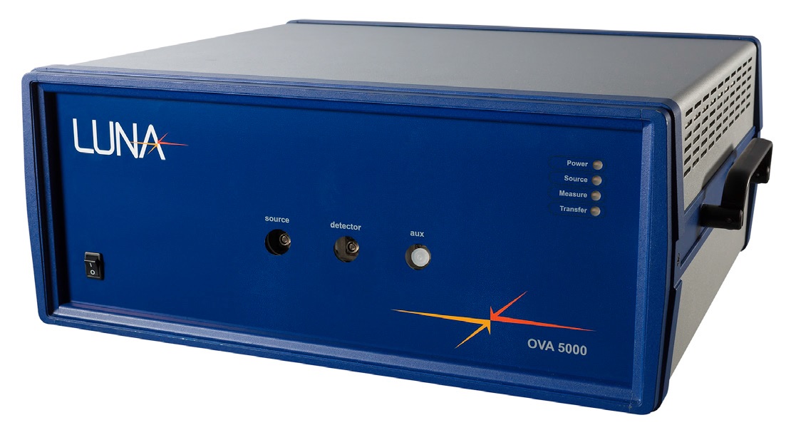
OVA 5000 Optical Vector Analyzers
Single-scan, All-parameter Measurement; 1270-1610 nm; Wavelength Resolution 1.6 pm; Loss Measurement Dynamic Range 60, 80 dB; Loss Measurement Resolution ±0.002, ±0.05 dB Luna’s OVA 5000 Optical Vector Analyzer™ is the fastest, most accurate and economical tool for loss, dispersion and polarization measurements of modern optical networking equipment – and the only instrument on the market that is capable of full and complete all-parameter linear characterization of single-mode optical components in a single scan. The OVA 5000 provides comprehensive component characterization of dispersion compensation modules, AWGs, Fiber Bragg Gratings and many other optical devices. The OVA 5000 uses an interferometric method to directly measure the linear transfer function (Jones Matrix) and simultaneously measure its four complex elements at every wavelength. From this data, all standard linear parameter measurements can be extracted with the highest dynamic range and accuracy available. The result is an extremely fast, high-resolution and accurate device characterization that is ideal for silicon photonics and other integrated photonics devices. The OVA 5000 simultaneously performs these optical component characterizations every 3 seconds: Insertion Loss (IL) Return Loss (RL) Dependent Loss (PDL) Phase Response Group Delay (GD) Chromatic Dispersion (CD) Polarization Mode Dispersion (PMD) / Second Order PMD Min/Max Loss Due to Polarization Impulse Response Jones Matrix Elements Phase Ripple – Linear and Quadratic With the optical frequency domain reflectometer (OFDR) option, the OVA 5000 optical vector analyzer can also operate as a high-resolution reflectometer , delivering reflectometer measurements with 20 μm sampling resolution, “zero dead zone” and high sensitivity (>95 dB). An optional polarization analysis software add-on allows the OVA 5000 to measure, calculate and display the response of an optical component to simulated input polarization states, eliminating the tedious and difficult task of polarization alignment. Key Features: Single Measurement, All-parameter Analysis of Devices up to 150 m in Length Full Characterization of Passive Devices in Under 3 s Complete Polarization Response Simultaneously Measure Complete Range of Parameters in One Single Scan: IL, RL, PDL, PMD, Second Order PMD, CD, GD, OTD Response, Jones Matrix Elements, Optical Phase Response High-Resolution C and L Band (OVA 5000) or O Band (OVA 5013) Capability Fast and Averaging Modes Real-time Measurements User-friendly Interface Wavelength Range: 1270 to 1610 nm Wavelength Resolution: 1.6 pm Loss Measurement Dynamic Range: 60, 80 dB Loss Measurement Resolution: ±0.002, ±0.05 dB Applications: Analyze Planar Light Circuits and Silicon Photonic Devices; Characterize Optical Fiber Components; Measure Both Spectral Response and Time Delay Response; Improve Device Simulations and Models With Complete Transfer Function
REQUEST PRICING AND AVAILABILITY
- Get your individual quote.
- Technical compatibility review included.
- Volume discounts available.
No obligation. Direct access to our engineering team.

PDLE-101 PDL Emulator
PDL Dynamic Range 0.1-20 dB; PDL Resolution 0.1 dB; C-, L-Band; Max. IL 2 dB; PDL Switching Time ≤5 ms; Residual PDM <0.1 ps; RL >50 dBHigh-speed fiber optic transceivers, including those deploying coherent detection technology for 40 Gbit/s and 100 Gbit/s data transmission, must meet stringent PDL (polarization dependent loss) tolerance specifications. In addition, the PDL tracking speed and response time of the PDL mitigation algorithm of a coherent detection receiver must be quantified.Lunas’ PDLE-101 PDL emulator is specially designed for such PDL-related tests. This PDL source/ emulator can generate individual PDL values between 0 and 20 dB, with a resolution of 0.1 dB for PDL tolerance testing. It can also generate variable PDL with user defined range, waveform, and speed for PDL tracking speed and recovery time tests.The PDLE-101 PDL emulator can be controlled via the front panel keypad or by remote control via USB, RS-232, GPIB, or Ethernet interfaces. The residual PMD of the unit is less than 0.1 ps.Key Features:High PDL (Polarization Dependent Loss) Resolution: 0.1 dBWide PDL Dynamic Range: 0.1 to 20 dBHigh Speed, PDL Switching Time: 5 ms max., 1 ms typ.PDL Waveforms: Sine, Square, TriangleRandom PDL GenerationWavelength Range: C-Band or L-BandMax. Insertion Loss (IL): 2 dB @ PDL = 0, Excluding ConnectorsLow Residual PMD: <0.1 ps @ PDL = 0Return Loss: >50 dBFiber Type: SMF-28Fiber Connector Type: FC/PC, FC/APC, SC/PC, SC/APCOptical Power Handling: 500 mWApplications: PDL Tolerance Test; PDL Tracking Speed and Recovery Time Tests; PDL Emulation; Code Development for PDL Compensation in Coherent Systems; System PDL Response Test
REQUEST PRICING AND AVAILABILITY
- Get your individual quote.
- Technical compatibility review included.
- Volume discounts available.
No obligation. Direct access to our engineering team.
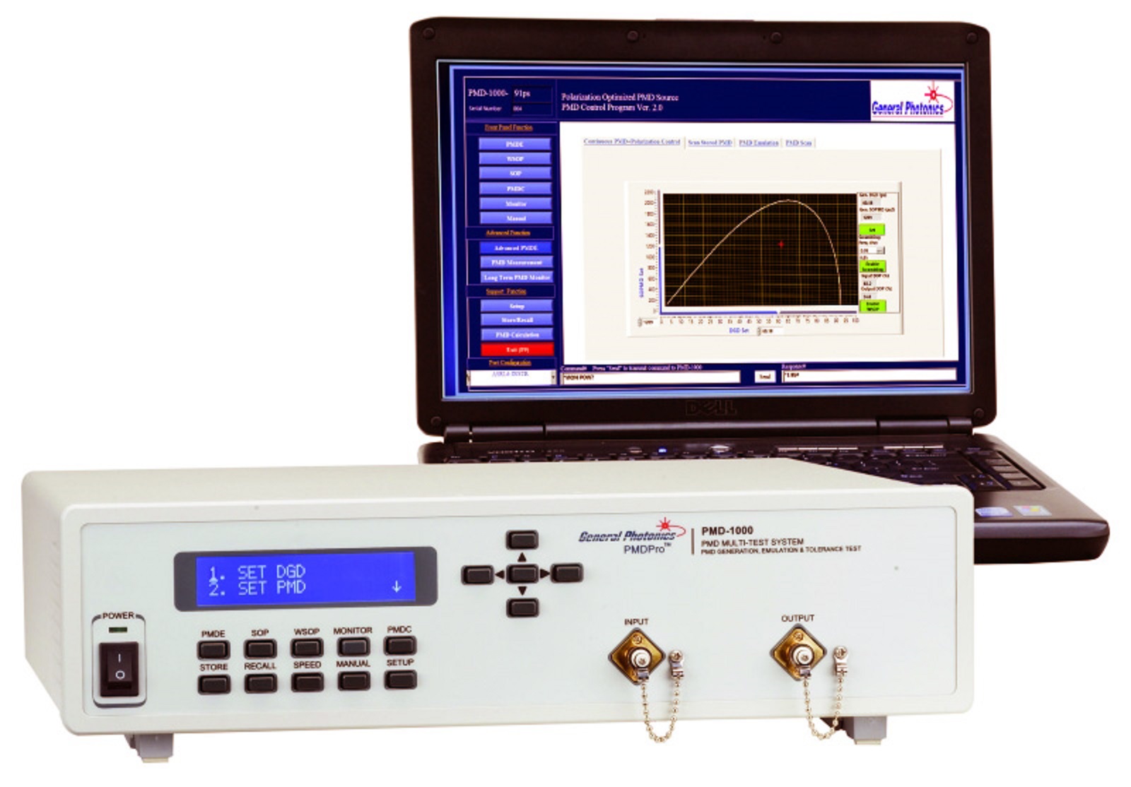
PMD-1000 PMD Source
PMD Range 1st Order 0-91, 0.36-182.4 ps, 2nd Order 2,000, 8,100 ps²; PMD Switching Time 1 ms; C-, L-Band; IL 5.0, 5.5 dB; PDL 0.45, 0.5 dB; RL 50 dBLunas’ PMD-1000 is a flexible, digital PMD (polarization mode dispersion) source that deterministically generates precise 1st order PMD up to 180 ps and 2nd order PMD up to 8,100 ps2. Its quasi-continuous operation mode enables independent generation of first order and wavelength-independent second order PMD for uniform coverage of the PMD space.The PMD-1000 uses high-speed ternary magneto optic crystals to generate PMD. The PMD switching time is as short as one millisecond, making the PMD-1000 the fastest PMD generator on the market.Its automatic polarization controller combined with before and after polarimeters enhances the instrument’s flexibility. For example, if the polarization controller is used to align and maintain the input SOP (state of polarization) at 45° from the principal axis of the DGD (differential group delay) element, the instrument creates the worst-case first order PMD effect.Alternatively, the controller can adjust and maintain the input SOP using the feedback from the rear polarimeter to either minimize or maximize the output DOP (degree of polarization) for each PMD setting. Minimizing the output DOP enables testing of the worst-case total PMD effect, while maximizing the DOP turns the PMD-1000 into a PMD compensator, allowing the user to obtain optimized PMD values for PMD compensation.The PMD-1000 can also perform PMD emulation by generating statistical PMD distributions. Finally, the system’s polarization controller and polarimeters enable variable rate scrambling and deterministic polarization control functions, including trace generation and polarization stabilization at any SOP. Lunas’ PMD-1000 makes your PMD-related systems testing simple, fast and professional.Key Features:All Digital Design – No MotorsHigh-speed PMD Switching: 1 ms1st and 2nd Order PMD Source/Emulator1st Order PMD Range: 0 to 91 ps, 0.36 to 182.4 ps2nd Order PMD Range: 2,000, 8,100 ps²Polarization ScramblingAutomatic Polarization AlignmentPMD CompensationOperating Wavelength Range: C-Band or L-BandInsertion Loss (IL): 5.0, 5.5 dBInput Power Range: -10 to 10 dBmReturn Loss ((RL): 50 dBPolarization Dependent Loss (PDL): 0.45, 0.5 dB typ.SOP Tracking Speed: 10 π/sDOP Accuracy: ±2%Optical Power Handling: 300 mW min.Applications: Verifying System PMD Tolerance; Stress Test of PMD Compensation Circuits; PMDC Optimization; Calibration Source for PMD Instruments; System PMD Emulation
REQUEST PRICING AND AVAILABILITY
- Get your individual quote.
- Technical compatibility review included.
- Volume discounts available.
No obligation. Direct access to our engineering team.