
Capacitors

AR Series Water-Cooled Oil-Filled Film Capacitors
6.0 µF to 1400 µF; 750 kv to 1250 kv; 300 kVA to 1600 kVA High capacitance at high power 6 to 1,400 µF capacitance 800 to 1,250 VRMS 240 to 2,000 ARMS 300 to 2,000 kVA Up to 25 kHz These oil-filled, water-cooled capacitors are aimed at particularly demanding applications such as high-voltage systems, pulsed lasers or induction heating. Select the right component from our portfolio of oil-filled capacitors. We offer a wide range of standard packing components and internal structures that make the capacitors suitable for energy storage, DC filtering, transient snubbing and high alternating current applications. The standard types offered here do not provide the solution to your challenge? We design, manufacture and test customized oil-filled capacitors according to your specifications - please contact us!
REQUEST PRICING AND AVAILABILITY
- Get your individual quote.
- Technical compatibility review included.
- Volume discounts available.
No obligation. Direct access to our engineering team.

CC Series Oil-Filled Film Capacitors
1 µF to 20 µF; 2,000 kv to 10,000 kv DC Filter Capacitors 1 to 20 µF capacitance Voltage 2,000 to 10,000 VDC Plated drawn steel cans Our oil-filled capacitors are aimed at particularly demanding applications such as high-voltage systems, pulsed lasers or induction heating. Select the right component from our portfolio of oil-filled capacitors. We offer a wide range of standard packing components and internal structures that make the capacitors suitable for energy storage, DC filtering, transient snubbing and high alternating current applications. The standard types offered here do not provide the solution to your challenge? We design, manufacture and test customized oil-filled capacitors according to your specifications - please contact us! Specifications Capacitance Range 1 to 20 µF Capacitance Tolerance ± 10 % standard, other tolerances available Operating Temperature -40 °C to +90 °C Insulation Resistance 25,000 MΩ•µF at 25 °C typical AC Ripple Voltage The sum of the DC voltage and peak AC ripple should not exceed the capacitor’s VDC rating. Additionally, the AC component should not exceed: 20 % of VDC at 60 Hz; 10 % of VDC at 400Hz; 5 % of VDC at 1 kHz; 1 % of VDC at 10 kHz Can Construction Drawn plated steel, epoxy paint optional Dielectric Kraft paper and polypropylene with environmentally compatible impregnant
REQUEST PRICING AND AVAILABILITY
- Get your individual quote.
- Technical compatibility review included.
- Volume discounts available.
No obligation. Direct access to our engineering team.

CHD Series Metallized Film Capacitors
0.01 µF to 0.33 µF ; VMAX 700 kV; SMAX 150 kVA 700 VRMS Working Voltage 150 kVA Max Power 250 ARMS Max Current Conduction Cooled Series & Parallel Stackable This series of metallized film capacitors basically consists of a wound core soldered between copper terminals. This wound core is composed of two metallic electrodes separated by an insulating dielectric, a thin film of polypropylene. Among the many possible types of core windings in our wide range of metallized film capacitors, the engineers select the type that optimizes the component for a particular mission profile. Due to the materials selected and the special design, these high power capacitors are very robust and reliable (self-healing). The metallized film capacitors offer high capacitance in a small package and allow for parallel or serial stacking. They are conduction cooled, can pass high reactive currents without failure withstand very significant voltage potentials without damage. Specifications Capacitance Range 0.1 to 0.2 µF standard; 0.01 to 0.33 custom Capacitance Tolerance ± 10 % standard, other tolerances available Dimensions 68 x 33 x 22.5 mm, 2 11/16 x 1 5/32 x 7/8 inch Weight 0.2 kg; .44 lb Operating Temperature Up to +90 °C Cooling method Conduction-cooled by bus bars Dissipation Factor 0.1 % Maximum Stray Inductance less than 5 nH
REQUEST PRICING AND AVAILABILITY
- Get your individual quote.
- Technical compatibility review included.
- Volume discounts available.
No obligation. Direct access to our engineering team.

CHE Series Metallized Film Capacitors
0.2 µF to 2.0 µF ; 525 kV to 700 kv; 325 kVA to 400 kVA Up to 700 VRMS Working Voltage Up to 400 kVA Max Power Up to 800 ARMS Max Current Conduction Cooled Series & Parallel Stackable This series of metallized film capacitors basically consists of a wound core soldered between copper terminals. This wound core is composed of two metallic electrodes separated by an insulating dielectric, a thin film of polypropylene. Among the many possible types of core windings in our wide range of metallized film capacitors, the engineers select the type that optimizes the component for a particular mission profile. Due to the materials selected and the special design, these high power capacitors are very robust and reliable (self-healing). The metallized film capacitors offer high capacitance in a small package and allow for parallel or serial stacking. They are conduction cooled, can pass high reactive currents without failure withstand very significant voltage potentials without damage. Specifications Capacitance Range 0.2 to 2.0 µF standard; 0.01 to 0.33 custom Capacitance Tolerance ± 10 % standard, other tolerances available Dimensions 70 x 57 x 41 mm, 2 3/4 x 2 1/4 x 2 5/8 inch Weight 0.5 kg; 1.1 lb Operating Temperature Up to +90 °C Cooling method Conduction-cooled by bus bars Dissipation Factor 0.1 % Maximum Stray Inductance less than 5 nH
REQUEST PRICING AND AVAILABILITY
- Get your individual quote.
- Technical compatibility review included.
- Volume discounts available.
No obligation. Direct access to our engineering team.

CHG Series Metallized Film Capacitors
0.1 µF to 1.32 µF ; 500 kV to 1000 kv; SMAX 300 kVA Up to 700 VRMS Working Voltage 600 kVA Max Power Up to 525 ARMS Max Current Conduction Cooled Series & Parallel Stackable This series of metallized film capacitors basically consists of a wound core soldered between copper terminals. This wound core is composed of two metallic electrodes separated by an insulating dielectric, a thin film of polypropylene. Among the many possible types of core windings in our wide range of metallized film capacitors, the engineers select the type that optimizes the component for a particular mission profile. Due to the materials selected and the special design, these high power capacitors are very robust and reliable (self-healing). The metallized film capacitors offer high capacitance in a small package and allow for parallel or serial stacking. They are conduction cooled, can pass high reactive currents without failure withstand very significant voltage potentials without damage. Specifications Capacitance Range 0.18 to 1.2 µF standard; 0.01 to 0.33 custom Capacitance Tolerance ± 10 % standard, other tolerances available Dimensions 49 x 49 x 30 mm, 1 15/16 x 1 15/16 x 1 3/16 inch Weight 0.25 kg; 0.5 lb Operating Temperature Up to +90 °C Cooling method Conduction-cooled by bus bars Dissipation Factor 0.1 % Maximum Stray Inductance less than 5 nH
REQUEST PRICING AND AVAILABILITY
- Get your individual quote.
- Technical compatibility review included.
- Volume discounts available.
No obligation. Direct access to our engineering team.

CHH Series Metallized Film Capacitors
0.1 µF to 2.5 µF ; 400 kV to 700 kv; SMAX 160 kVA Up to 700 VRMS Working Voltage160 kVA Max PowerUp to 625 ARMS Max CurrentConduction CooledSeries & Parallel Stackable This series of metallized film capacitors basically consists of a wound core soldered between copper terminals. This wound core is composed of two metallic electrodes separated by an insulating dielectric, a thin film of polypropylene. Among the many possible types of core windings in our wide range of metallized film capacitors, the engineers select the type that optimizes the component for a particular mission profile. Due to the materials selected and the special design, these high power capacitors are very robust and reliable (self-healing). The metallized film capacitors offer high capacitance in a small package and allow for parallel or serial stacking. They are conduction cooled, can pass high reactive currents without failure withstand very significant voltage potentials without damage. Specifications Capacitance Range 0.1 to 2.5 µF standard; 0.01 to 0.33 custom Capacitance Tolerance ± 10 % standard, other tolerances available Dimensions 68 x 30.2 x 30.2 mm, 2 11/16 x 1 3/16 x 1 3/16 inch Weight 0.5 kg; 1.1 lb Operating Temperature Up to +90 °C Cooling method Conduction-cooled by bus bars Dissipation Factor 0.1 % Maximum Stray Inductance less than 5 nH
REQUEST PRICING AND AVAILABILITY
- Get your individual quote.
- Technical compatibility review included.
- Volume discounts available.
No obligation. Direct access to our engineering team.

CHJ Series Metallized Film Capacitors
0.18 µF to 5.0 µF ; 300 kV to 700 kv; 180 kVS to 210 kVA Up to 700 VRMS Working Voltage Up to 210 kVA Max Power Up to 600 ARMS Max Current Conduction Cooled Series & Parallel Stackable This series of metallized film capacitors basically consists of a wound core soldered between copper terminals. This wound core is composed of two metallic electrodes separated by an insulating dielectric, a thin film of polypropylene. Among the many possible types of core windings in our wide range of metallized film capacitors, the engineers select the type that optimizes the component for a particular mission profile. Due to the materials selected and the special design, these high power capacitors are very robust and reliable (self-healing). The metallized film capacitors offer high capacitance in a small package and allow for parallel or serial stacking. They are conduction cooled, can pass high reactive currents without failure withstand very significant voltage potentials without damage. Specifications Capacitance Range 0.18 to 5.0 µF standard; 0.01 to 0.33 custom Capacitance Tolerance ± 10 % standard, other tolerances available Dimensions 76.2 x 50.8 x 36.5 mm, 3 x 2 x 1 7/16 inch Weight 0.27 kg; 0.6 lb Operating Temperature Up to +90 °C Cooling method Conduction-cooled by bus bars Dissipation Factor 0.1 % Maximum Stray Inductance less than 5 nH
REQUEST PRICING AND AVAILABILITY
- Get your individual quote.
- Technical compatibility review included.
- Volume discounts available.
No obligation. Direct access to our engineering team.

CHL Series Metallized Film Capacitors
0.1 µF to 2.5 µF ; 400 kV to 700 kv; SMAX 160 kVA Up to 700 VRMS Working Voltage 160 kVA Max Power Up to 400 ARMS Max Current Conduction Cooled Series & Parallel Stackable This series of metallized film capacitors basically consists of a wound core soldered between copper terminals. This wound core is composed of two metallic electrodes separated by an insulating dielectric, a thin film of polypropylene. Among the many possible types of core windings in our wide range of metallized film capacitors, the engineers select the type that optimizes the component for a particular mission profile.Due to the materials selected and the special design, these high power capacitors are very robust and reliable (self-healing). The metallized film capacitors offer high capacitance in a small package and allow for parallel or serial stacking. They are conduction cooled, can pass high reactive currents without failure withstand very significant voltage potentials without damage. Specifications Capacitance Range 0.1 to 2.5 µF standard; 0.01 to 0.33 custom Capacitance Tolerance ± 10 % standard, other tolerances available Dimensions 68 x 32 x 30.2 mm, 2 11/16 x 1 1/4 x 1 3/16 inch Weight 0.5 kg; 1.1 lb Operating Temperature Up to +90 °C Cooling method Conduction-cooled by bus bars Dissipation Factor 0.1 % Maximum Stray Inductance less than 5 nH
REQUEST PRICING AND AVAILABILITY
- Get your individual quote.
- Technical compatibility review included.
- Volume discounts available.
No obligation. Direct access to our engineering team.

CHM Series Metallized Film Capacitors
0.1 µF to 2.5 µF ; 400 kV to 700 kv; SMAX 160 kVA Up to 700 VRMS Working Voltage 60 kVA Max Power Up to 400 ARMS Max Current Conduction Cooled Series & Parallel Stackable This series of metallized film capacitors basically consists of a wound core soldered between copper terminals. This wound core is composed of two metallic electrodes separated by an insulating dielectric, a thin film of polypropylene. Among the many possible types of core windings in our wide range of metallized film capacitors, the engineers select the type that optimizes the component for a particular mission profile. Due to the materials selected and the special design, these high power capacitors are very robust and reliable (self-healing). The metallized film capacitors offer high capacitance in a small package and allow for parallel or serial stacking. They are conduction cooled, can pass high reactive currents without failure withstand very significant voltage potentials without damage. Specifications Capacitance Range 0.1 to 2.5 µF standard; 0.01 to 0.33 custom Capacitance Tolerance ± 10 % standard, other tolerances available Dimensions 70 x 32 x 30.2 mm, 23/4 x 11/4 x 13/16 inch Weight 0.5 kg; 1.1 lb Operating Temperature Up to +90 °C Cooling method Conduction-cooled by bus bars Dissipation Factor 0.1 % Maximum Stray Inductance less than 5 nH
REQUEST PRICING AND AVAILABILITY
- Get your individual quote.
- Technical compatibility review included.
- Volume discounts available.
No obligation. Direct access to our engineering team.

CHN0 Series Metallized Film Capacitors
1.4 µF to 10 µF; 600 kV to 650 kv; SMAX 250 kVA Up to 650 VRMS Working Voltage 250 kVA Max Power Up to 600 ARMS Max Current Conduction Cooled Up to 10 µF This series of metallized film capacitors basically consists of a wound core soldered between copper terminals. This wound core is composed of two metallic electrodes separated by an insulating dielectric, a thin film of polypropylene. Among the many possible types of core windings in our wide range of metallized film capacitors, the engineers select the type that optimizes the component for a particular mission profile. Due to the materials selected and the special design, these high power capacitors are very robust and reliable (self-healing). The metallized film capacitors offer high capacitance in a small package and allow for parallel or serial stacking. They are conduction cooled, can pass high reactive currents without failure withstand very significant voltage potentials without damage. Specifications Capacitance Range 1.4 to 10 µF Capacitance Tolerance ± 10 % standard, other tolerances available Dimensions 80 mm (maximum) diameter x 70 mm high, 31/8 (maximum) diameter x 23/4 high Weight .75 kg; 1.7 lb Operating Temperature Up to +90 °C Cooling method Conduction-cooled by bus bars Dissipation Factor 0.1 % Maximum Stray Inductance less than 5 nH
REQUEST PRICING AND AVAILABILITY
- Get your individual quote.
- Technical compatibility review included.
- Volume discounts available.
No obligation. Direct access to our engineering team.

CHN6 Series Metallized Film Capacitors
0.03 µF to 1.2 µF; 450 kV to 1000 kv; SMAX 120 kVA Up to 1000 VRMS Working Voltage 120 kVA Max Power Up to 125 ARMS Max Current Conduction Cooled This series of metallized film capacitors basically consists of a wound core soldered between copper terminals. This wound core is composed of two metallic electrodes separated by an insulating dielectric, a thin film of polypropylene. Among the many possible types of core windings in our wide range of metallized film capacitors, the engineers select the type that optimizes the component for a particular mission profile. Due to the materials selected and the special design, these high power capacitors are very robust and reliable (self-healing). The metallized film capacitors offer high capacitance in a small package. They are conduction cooled, can pass high reactive currents without failure withstand very significant voltage potentials without damage. Specifications Capacitance Range 0.025 to 1.2 µF Capacitance Tolerance ± 10 % standard, other tolerances available Dimensions 30 mm diameter x 29 mm high, 1 3/16 “ diameter x 1 1/8 “ high Weight .15 kg; .33 lb Operating Temperature Up to +90 °C Cooling method Conduction-cooled by bus bars Dissipation Factor 0.1 % Maximum Stray Inductance less than 5 nH
REQUEST PRICING AND AVAILABILITY
- Get your individual quote.
- Technical compatibility review included.
- Volume discounts available.
No obligation. Direct access to our engineering team.

CHX Series Water-Cooled Film Capacitors
0.06 µF to 0.69; VMAX 1500 kv; SMAX 300 kVA 1500 VRMS Working Voltage 300 kVA Max Power Up to 200 ARMS Max Current Water-Cooled This series of water cooled metallized film capacitors basically consists of a wound core soldered between copper terminals. This wound core is composed of two metallic electrodes separated by an insulating dielectric, a thin film of polypropylene. Among the many possible types of core windings in our wide range of metallized film capacitors, the engineers select the type that optimizes the component for a particular mission profile. Due to the materials selected and the special design, these high power capacitors are very robust and reliable (self-healing). The metallized film capacitors offer high capacitance in a small package. They are water cooled, can pass high reactive currents without failure withstand very significant voltage potentials without damage. Specifications Capacitance Range 0.06 µF standard; up to 0.069 µF custom Capacitance Tolerance ± 10 % standard, other tolerances available Dimensions 53 mm diameter x 71 mm high, 2 1/16 “ diameter x 2 13/16 “ high Weight .36 kg; .79 lb Operating Temperature Up to +90 °C Cooling method Individually water-cooled Dissipation Factor 0.1 % Maximum Stray Inductance less than 5 nH
REQUEST PRICING AND AVAILABILITY
- Get your individual quote.
- Technical compatibility review included.
- Volume discounts available.
No obligation. Direct access to our engineering team.

CP Series Oil-Filled Film Capacitors
0.01 µF to 1 µF; 10,000 kv to 100,000 kv DC Filter Capacitors 0.01 to 1 µF capacitance Voltage 10,000 to 100,000 VDC Welded Polypropylene cases Our oil-filled capacitors are aimed at particularly demanding applications such as high-voltage systems, pulsed lasers or induction heating. Select the right component from our portfolio of oil-filled capacitors. We offer a wide range of standard packing components and internal structures that make the capacitors suitable for energy storage, DC filtering, transient snubbing and high alternating current applications. The standard types offered here do not provide the solution to your challenge? We design, manufacture and test customized oil-filled capacitors according to your specifications - please contact us! Specifications Capacitance Range 0.01 to 1 µF Capacitance Tolerance ± 10 % standard, other tolerances available Operating Temperature -40 °C to +90 °C Insulation Resistance 25,000 MΩ•µF at 25 °C typical AC Ripple Voltage The sum of the DC voltage and peak AC ripple should not exceed the capacitor’s VDC rating. Additionally, the AC component should not exceed: 20 % of VDC at 60 Hz, 10 % of VDC at 400Hz, 5 % of VDC at 1 kHz, 1 % of VDC at 10 kHz Case Construction Welded Polypropylene plastic Dielectric Kraft paper and polypropylene with environmentally compatible impregnant
REQUEST PRICING AND AVAILABILITY
- Get your individual quote.
- Technical compatibility review included.
- Volume discounts available.
No obligation. Direct access to our engineering team.

EPSL Series Ceramic Capacitors
180 pF to 16,000 pF; 6 kV to 40 kV Features Designed For High Voltage DC-Blocking High Capacitance Values in Small Size Rugged & Epoxy Encapsulated High-Torque Terminals Available Class II X5U Dielectric Specifications Temperature Range Operating: -55 °C to +85 °C Storage: -55 °C to +125 °C Capacitance Tolerance +80 %, -20 % standard Dissipation Factor 1.5 % Maximum when measured at a frequency of 1 kHz and 25 °C Dielectric Characteristic Class II X5U (+22 %, -56 % capacitance change with temperature over -55 °C to +85 °C) Dielectric Strength Will withstand a DC potential of 1.5 times VMAX rating for 10 Seconds at 25 °C Insulation Resistance 20,000 Megohms (MΩ) Minimum at 100 VDC Terminal Strength Maximum applied torque to be 12 inch-pounds or less (standard S terminal) Maximum applied torque to be 25 inch-pounds or less (high-strength H terminal) Humidity Protection Epoxy encapsulated Standard Markings “HEC”, Capacitance, Tolerance, Rated Working Voltage (VDC) and Date Code
REQUEST PRICING AND AVAILABILITY
- Get your individual quote.
- Technical compatibility review included.
- Volume discounts available.
No obligation. Direct access to our engineering team.

EPSP Pulse Power Ceramic Capacitors
500 pF to 4,000 pF; 20 kV to 52 kV The EPSP Series of pulse power ceramic capacitors are optimized for sourcing and sinking short-duration high-current pulses. They are ideal components for use in pulsed gas laser systems, HVDC power supplies, lightning arrestor systems, electrostatic copying machines and electron microscopes. They utilize an N5500 temperature characteristic Class 1 dielectric to achieve a very low dissipation factor coupled with a very high capacitance-per-volume and an absence of etectable piezoelectric or electrorestrictive effects. Epoxy encapsulation provides excellent insulation resistance and a physically robust package. Specification Temperature Range Operating: -30 °C to +50 °C Storage: -30 °C to +50 °C Capacitance Tolerance ± 20 % standard; other tolerances available Dissipation Factor 0.5 % Maximum when measured at a frequency of 1 kHz Dielectric Characteristic Class I N5500 (± 1000 ppm/ °C) over the Operating Temperature range Dielectric Strength Will withstand a DC potential of VTEST (listed above) for 10 Seconds at 25 °C Insulation Resistance 20,000 Megohms (MΩ) Minimum at 100 VDC Terminal Strength Maximum applied torque to be 20 inch-pounds or less Humidity Protection Epoxy encapsulated Standard Markings “HEC”, Capacitance, Tolerance, Rated Working Voltage (VDC), TC and Date Code
REQUEST PRICING AND AVAILABILITY
- Get your individual quote.
- Technical compatibility review included.
- Volume discounts available.
No obligation. Direct access to our engineering team.

EPSR Series High Voltage Pulse Power Ceramic Capacitors
700 pF to 4,000 pF; 20 kV to 40 kV High Energy Corporation's new line of Epoxy Encapsulated Ceramic Capacitors are designed for use in HVDC Power Supplies, electrostatic copying machines, lightning arrestor systems, electron microscopes and many laser applications. These capacitors feature a class I ceramic dielectric, low dissipation factor, and small case size. Specification Temperature Operating -300 °C to +500 °C Range: storage -300 °C to +500 °C Capacitance listed as +/- 20 %, other values Tolerance: available Dissipation 0.5 % maximum, when MeaFactor: sured at a frequency of 1 KHz. Dielectric all capacitors will withstand a strength DC test voltage, as listed, for test: 10 sec. at a temp. of 250 °C
REQUEST PRICING AND AVAILABILITY
- Get your individual quote.
- Technical compatibility review included.
- Volume discounts available.
No obligation. Direct access to our engineering team.
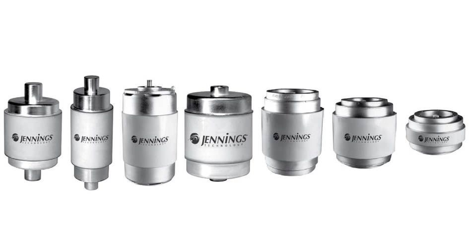
Fixed Vacuum Capacitors
25 to 2,000 pF; 4.5 to 33 kV Vacuum capacitors for high voltage and high frequency applications offer long, maintenance-free service life and the ability to withstand transients that destroy other types of capacitors. Vacuum assures oxidation-free surfaces and a dielectric that is self-healing when subject to transient over-voltage conditions. This series of fixed vacuum capacitors offers capacitances of 25 to 2,000 pF, withstanding working voltages at 50/60 Hz in the range of 4.5 to 33 kV. In addition to this working voltage, a value for AC test voltage is quoted in this series’ product specifications. The maximum operating current for vacuum capacitors is limited by temperature rise and working voltage. A current vs. frequency chart is provided for each capacitor. If none of our standard catalog models meet your needs, our supplier`s engineers are happy to work with you to design a custom solution that meets your specific requirements. Capacitance Tolerance: Fixed capacitors with a nominal capacitance above 50 pF shall be within ±5%. Capacitors with a nominal capacitance of 50 pF or less shall be within ±10%, or 0.5 pF, whichever is greater. Testing Standards: All capacitors are factory tested for dielectric strength on a 100% basis prior to shipment, using a low current, high potential source at 60 Hz voltage. Upon customer request, certified test reports will be made available. Key Features: High Voltage Rating High RF Current Ratings for normal convection cooling in ambient temperature of +25 °C (unless otherwise specified) Maximum Allowable Temperature: +125 °C Low Losses Self-healing High Altitude Operation Mounting Position: Any Typical Applications: Broadcast Radio Transmitters; Semiconductor Manufacturing Equipment; Plasma Generating Equipment; Industrial Dielectric Heating Equipment; Power Switching and Interrupting; Avionic and Mobile Radio Systems; Radar Antenna Switching; MRI and NMR; High Voltage Capacitor Banks
REQUEST PRICING AND AVAILABILITY
- Get your individual quote.
- Technical compatibility review included.
- Volume discounts available.
No obligation. Direct access to our engineering team.

HH57 & HH58 Series Ceramic Capacitors
500 pF to 2,500 pF; 7.5 kV to 15 kV; 0.6 kVA to 35 kVA; Class II Dielectrics Features Compact High Capacitance Parts 7.5 and 15 kVDC Power Ratings Broadcast Barrel Package Metric or English Terminals Three Class II Dielectrics Specifications Temperature Range Operating: -55 °C to +85 °C Storage: -55 °C to +125 °C Capacitance Tolerance ± 10 % or ± 20 % standard Dissipation Factor 1.5 % Maximum when measured at a frequency of 1 kHz and 25 °C Dielectric Characteristic Class II X5T (+22 %, -33 % capacitance change with temperature over -55 °C to +85 °C), or X5U (+22 %, -56 % capacitance change with temperature over -55 °C to +85 °C), or X5V (+22 %, -82 % capacitance change with temperature over -55 °C to +85 °C) Dielectric Strength Will withstand an AC potential of 1.5 times Rated Working Voltage for 10 Seconds at 25 °C. Insulation Resistance 10,000 Megohms (MΩ) Minimum at 100 VDC Terminals Silver Plated Terminal Strength Maximum applied torque to be 20 inch-pounds or less (HH57 series), 6 inch-pounds or less (HH58 series with standard terminal), 17 inch-pounds or less (HH58 series with solid terminal) Humidity Protection Nonconductive Coating Standard Markings “HEC”, Capacitance, Tolerance, Rated Working Voltage (VDC) and Date Code
REQUEST PRICING AND AVAILABILITY
- Get your individual quote.
- Technical compatibility review included.
- Volume discounts available.
No obligation. Direct access to our engineering team.

HT50 & HT58 Series Ceramic Capacitors
10 pF to 700 pF; VMAX 7.5 kV; SMAX 10 kVA HT Series Ceramic Capacitors are small, RF-capable, Class 1 parts featuring high Voltage, Current and Power ratings. They exhibit a low dissipation factor and minimum self-inductance. These extremely rugged capacitors are carefully designed to live in the demanding world of broadcast and high-voltage industrial application. Their structure is both simple and robust, assuring a long trouble free life. HT Series parts feature a nonconductive, humidity-resistant, coating and a long flashover path. They are built upon a choice ofsix Class I dielectrics, providing a broad range of capacitance and temperature coefficients. Typical applications include transmitters, antennas, induction heating, X-ray, diathermy and welding. Specifications Temperature Range Operating: -55 °C to +85 °C Storage: -55 °C to +125 °C Capacitance Tolerance From ± 2.5 % to ± 20% and from ±2.5 pF to ±1 pF Dissipation Factor 0.1 % to 0.5 % Maximum (see Dielectric chart above) Dielectric Strength Will withstand an AC potential of 1.5 times Rated Working Voltage for 10 Seconds at 25 °C. Insulation Resistance 10,000 Megohms (MΩ) Minimum Terminals Silver Plated Terminal Strength Maximum applied torque to be 20 inch-pounds or less (HT57 & HT59 series), 6 inch-pounds or less (HT50 & HT58 series with standard terminal), 17 inch-pounds or less (HT 50 & HT58 series with solid terminal) Humidity Protection Nonconductive Coating Standard Markings “HEC”, Capacitance, Tolerance, Rated Working Voltage (VDC), TC and Date Code
REQUEST PRICING AND AVAILABILITY
- Get your individual quote.
- Technical compatibility review included.
- Volume discounts available.
No obligation. Direct access to our engineering team.

HT53, HT54, HT55 Series Ceramic Capacitors
1 pF to 45 pF; VMAX 5 kV; SMAX 3 kVA to 7 kVA HT Series Ceramic Capacitors are small, RF-capable, Class 1 parts featuring high Voltage, Current and Power ratings. They exhibit a low dissipation factor and minimum self-inductance. These extremely rugged capacitors are carefully designed to live in the demanding world of broadcast and high-voltage industrial application. Their structure is both simple and robust, assuring a long trouble free life. HT Series parts feature a nonconductive, humidity-resistant, coating and a long flashover path. They are built upon a choice ofsix Class I dielectrics, providing a broad range of capacitance and temperature coefficients. Typical applications include transmitters, antennas, induction heating, X-ray, diathermy and welding. Specificatons Temperature Range Operating: -55 °C to +85 °C Storage: -55 °C to +125 °C Capacitance Tolerance From ± 2.5 % to ± 20% and from ±2.5 pF to ±1 pF Dissipation Factor 0.1 % to 0.5 % Maximum (see Dielectric chart above) Dielectric Strength Will withstand an AC potential of 1.5 times Rated Working Voltage for 10 Seconds at 25 °C. Insulation Resistance 10,000 Megohms (MΩ) Minimum Terminals Silver Plated Terminal Strength Maximum applied torque to be 20 inch-pounds or less (HT57 & HT59 series). 6 inch-pounds or less (HT50 & HT58 series with standard terminal), 17 inch-pounds or less (HT 50 & HT58 series with solid terminal) Humidity Protection Nonconductive Coating Standard Markings “HEC”, Capacitance, Tolerance, Rated Working Voltage (VDC), TC and Date Code
REQUEST PRICING AND AVAILABILITY
- Get your individual quote.
- Technical compatibility review included.
- Volume discounts available.
No obligation. Direct access to our engineering team.

HT57 Series Ceramic Capacitors
10 pF to 500 pF; VMAX 15 kV; SMAX 35 kVA HT Series Ceramic Capacitors are small, RF-capable, Class 1 parts featuring high Voltage, Current and Power ratings. They exhibit a low dissipation factor and minimum self-inductance. These extremely rugged capacitors are carefully designed to live in the demanding world of broadcast and high-voltage industrial application. Their structure is both simple and robust, assuring a long trouble free life. HT Series parts feature a nonconductive, humidity-resistant, coating and a long flashover path. They are built upon a choice ofsix Class I dielectrics, providing a broad range of capacitance and temperature coefficients. Typical applications include transmitters, antennas, induction heating, X-ray, diathermy and welding. Specifications Temperature Range Operating: -55 °C to +85 °C Storage: -55 °C to +125 °C Capacitance Tolerance From ± 2.5 % to ± 20 % and from ±2.5 pF to ±1 pF Dissipation Factor 0.1 % to 0.5 % Maximum (see Dielectric chart above) Dielectric Strength Will withstand an AC potential of 1.5 times Rated Working Voltage for 10 Seconds at 25 °C. Insulation Resistance 10,000 Megohms (MΩ) Minimum Terminals Silver Plated Terminal Strength Maximum applied torque to be 20 inch-pounds or less (HT57 & HT59 series), 6 inch-pounds or less (HT50 & HT58 series with standard terminal), 17 inch-pounds or less (HT 50 & HT58 series with solid terminal) Humidity Protection Nonconductive Coating Standard Markings “HEC”, Capacitance, Tolerance, Rated Working Voltage (VDC), TC and Date Code
REQUEST PRICING AND AVAILABILITY
- Get your individual quote.
- Technical compatibility review included.
- Volume discounts available.
No obligation. Direct access to our engineering team.

HT59 Series Ceramic Capacitors
50 pF to 1,500 pF; VMAX 25 kV; SMAX 50 kVA HT Series Ceramic Capacitors are small, RF-capable, Class 1 parts featuring high Voltage, Current and Power ratings. They exhibit a low dissipation factor and minimum self-inductance. These extremely rugged capacitors are carefully designed to live in the demanding world of broadcast and high-voltage industrial application. Their structure is both simple and robust, assuring a long trouble free life. HT Series parts feature a nonconductive, humidity-resistant, coating and a long flashover path. They are built upon a choice ofsix Class I dielectrics, providing a broad range of capacitance and temperature coefficients. Typical applications include transmitters, antennas, induction heating, X-ray, diathermy and welding. Specification Temperature Range Operating: -55 °C to +85 °C Storage: -55 °C to +125 °C Capacitance Tolerance From ± 2.5 % to ± 20 % and from ±2.5 pF to ±1 pF Dissipation Factor 0.1 % to 0.5 % Maximum (see Dielectric chart above) Dielectric Strength Will withstand an AC potential of 1.5 times Rated Working Voltage for 10 Seconds at 25 °C. Insulation Resistance 10,000 Megohms (MΩ) Minimum Terminals Silver Plated Terminal Strength Maximum applied torque to be 20 inch-pounds or less (HT57 & HT59 series), 6 inch-pounds or less (HT50 & HT58 series with standard terminal), 17 inch-pounds or less (HT 50 & HT58 series with solid terminal) Humidity Protection Nonconductive Coating Standard Markings “HEC”, Capacitance, Tolerance, Rated Working Voltage (VDC), TC and Date Code
REQUEST PRICING AND AVAILABILITY
- Get your individual quote.
- Technical compatibility review included.
- Volume discounts available.
No obligation. Direct access to our engineering team.

LC Series Oil-Filled Film Capacitors
1 µF to 10 µF; 10,000 kv to 40,000 kv DC Filter capacitors 1 to 20 µF capacitance Voltage 10,000 to 100,000 VDC Welded cans Our oil-filled capacitors are aimed at particularly demanding applications such as high-voltage systems, pulsed lasers or induction heating. Select the right component from our portfolio of oil-filled capacitors. We offer a wide range of standard packing components and internal structures that make the capacitors suitable for energy storage, DC filtering, transient snubbing and high alternating current applications. The standard types offered here do not provide the solution to your challenge? We design, manufacture and test customized oil-filled capacitors according to your specifications - please contact us! Specifications Capacitance Range 1 to 20 µF Capacitance Tolerance ± 10% standard, other tolerances available Operating Temperature -40 °C to +90 °C Insulation Resistance 25,000 MΩ•µF at 25 °C typical AC Ripple Voltage The sum of the DC voltage and peak AC ripple should not exceed the capacitor’s VDC rating. Additionally, the AC component should not exceed: 20 % of VDC at 60 Hz, 10 % of VDC at 400Hz, 5 % of VDC at 1 kHz, 1 % of VDC at 10 kHz Can Construction Welded stainless steel or mild steel with epoxy finish Dielectric Kraft paper and polypropylene with environmentally compatible impregnant
REQUEST PRICING AND AVAILABILITY
- Get your individual quote.
- Technical compatibility review included.
- Volume discounts available.
No obligation. Direct access to our engineering team.

PWC Water-cooled Ceramic Capacitors
400 pF to 10,000 pF; 10 kV to 25 kV; 1,000 kVA to 4,000 kVA; Water-cooled PWC Series Ceramic Capacitors are large water-cooled ‘pot’ style components providing current capacity to 300 Amperes and maximum reactive power ratings up to 4000 kVA. These parts feature a low dissipation factor Class I dielectric combined with superior structural strength coupled with the high thermodynamic efficiency of water-cooling to allow operation at extremely high power levels and high frequency. They are ideal for operation in the tank circuit of high power RF equipment. Popular applications include induction heating, dielectric heating and high-frequency welding equipment. Specifications Temperature Range Operating: -55 °C to +85 °C Storage: -55 °C to +125 °C Capacitance Tolerance Standard ± 20 % Optional ± 10 % Dissipation Factor 0.05 % Maximum Dielectric Strength Will withstand an AC potential of 1.4 times Rated Working Voltage for 10 Seconds at 25 °C. Insulation Resistance 10,000 Megohms (MΩ) Minimum Standard Markings “HEC”, Capacitance, Tolerance, Rated Working Voltage (VDC), Maximum Frequency, Maximum Reactive Power, Maximum Current and Date Code
REQUEST PRICING AND AVAILABILITY
- Get your individual quote.
- Technical compatibility review included.
- Volume discounts available.
No obligation. Direct access to our engineering team.