
Measurements of Passive Optics and Connectors

BM Backreflection Meters
Single and Dual Source; 633-1625 nm; Reflectance Dynamic Range -1--70 dB; Fiber Type SM, MM; 8° Angled NTT-FC/APC Receptacle OZ Optics’ BM series of backreflection meters measure the total accumulated optical return loss that is reflected back through a device or fiber under test. The measured reflections are caused by Rayleigh scattering, sudden changes in the refractive index within the device under test (DUT), or from connector ends. BM series meters are available as portable handheld devices (BM-100 and BM-200) or in a benchtop form factor (BM-1000 and BM-2000). The BM series backreflection meters are configured with an FC/APC connector on the output port, to minimize unwanted reflections. The meters have either one or two built-in laser diodes (plus a choice of SLEDs or LEDs for benchtop models) for return loss measurement at specific wavelengths. An optional detector can be added to the unit for insertion loss measurements. Reference patchcords for calibration are available. BM series meters cover a wide range of available wavelengths, thus providing measurement capabilities for non-telecom applications as well as telecom. BM-100/200 portable meters' wavelengths range from 8050 nm to 1625 nm, while the BM-1000/2000 benchtop meters are offered with special wavelengths, ranging from 633 nm to 1625 nm. The BM-1000/2000 benchtop backreflection meters feature a colour touchscreen display with a simple graphical user interface. The units come with a built-in memory that allows the user to store measured DUT test results. The BM series backreflection meters can be operated remotely via the built-in USB interface. A universal AC/DC power supply is included with all units. Reference patch cords for calibration are available. Adapter patch cords are also available, to allow the meter to be used with devices having different connectors. Key Features MB-100/200 Handheld Backreflection Meters: Built-in Single and Dual Laser Diode Source Built-in Single and Dual Laser Diode Source Dual Wavelength Source Available Sensitivity: Down to -70 dB Wide Range of Available Wavelenghts: 850 nm to 1625 nm Reflectance Dynamic Range: -1 dB to -70 dB Built-in USB Communications Port Fiber Type: Single Mode (SM), Multi Mode (MM) Receptacle: 8" Angled NTT-FC/APC Rugged and Compact Design High Resolution Optional Insertion Loss Measurement Capability Additional Key Features MB-1000/2000 Benchtop Backreflection Meters: Unique Wavelength Offerings for Speciality Applications Wide Range of Available Wavelengths: 633 nm to 1625 nm Broadband SLED for Imprived Stability Sensitivity: Down to -75 dB Touchscreen Display Built-in Memory Applications: Backreflection Measurement of Components; OCT Device Testing; Insertion Loss Measurement; End-to-end Loss Measurement; Quality Control; New Product Development; Component or System Troubleshooting; Network Installation
REQUEST PRICING AND AVAILABILITY
- Get your individual quote.
- Technical compatibility review included.
- Volume discounts available.
No obligation. Direct access to our engineering team.
DA-100 Variable Optical Attenuators
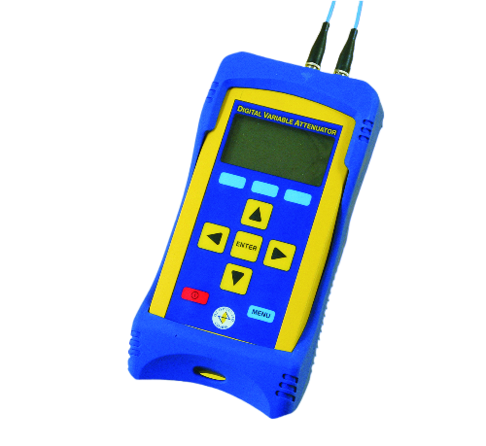
Hand-held Device; Fiber Type SM, MM, PM (PANDA); 350 to 2050 nm; Connector Type NTT-FC/PC, ST, SC, other; Attenuation IL to 40, 60 dB OZ Optics’ DA-100 series of compact, hand-held and rugged digital attenuators feature high resolution, high speed, high attenuation range and high power handling (blocking technique only). These CE approved attenuators have low insertion loss, low backreflection, low PDL and flat wavelength response. The DA-100 series of hand-held digital attenuators can be calibrated for up to four wavelengths, for C or L bands. Alternatively, the units can be calibrated for a continuous range. By using interpolation between the calibration wavelengths, the units are capable of providing accurate attenuation levels over a continuous, broad range of wavelengths. A computer interface allows users to access or remotely control the units through a PC. An optional, built-in rechargeable battery is available for field use, where AC power may not be readily accessible. OZ Optics provides digital attenuators that use either single mode, multi mode or polarization maintaining (PM) fiber. In general, OZ Optics uses polarization maintaining fibers based on the PANDA fiber structure when building polarization maintaining components and patchcords. However, OZ Optics can construct devices using other PM fiber structures. OZ Optics does carry some alternative fiber types in stock, so please contact AMS Technology for availability. If necessary, OZ Optics is willing to use customer supplied fibers to build devices. Key Features: CE Compliant, Hand-held Device Computer Interface (USB as Standard) Battery Option Available High Power Handling (up to 2 W) High Speed and Resolution- Wide Attenuation Range (from 350 to 2050 nm) Low PDL and Wavelength Dependency Low Insertion Loss and Backreflection Rugged and Compact Design Calibrated for Dual Wavelengths, (1300 to 1550 nm) or Calibrated for C and L Bands. Can also be Calibrated for up to Four Individual WavelengthsApplications: Bit Error Rate Testing; Trouble Shooting Receivers and Other Active Fiber Optic Components; Simulating Long Distance Fiber Transmission; Design of Fiber Optic Transmitter/Receiver Circuitry; Power Meter Linearity Checks; Power Setting
REQUEST PRICING AND AVAILABILITY
- Get your individual quote.
- Technical compatibility review included.
- Volume discounts available.
No obligation. Direct access to our engineering team.

DR-100 Digital Variable Reflectors
980 to 1625 nm; Reflectance Range 2 to 60 dB; Fiber Type SM, MM, PM; PDL 0.05, 0.08 dB; Optical Max. Power Level Continuous 500 mW (MM), 50 mW (SM) OZ Optics’ DR-100 series of digital variable reflectors enables the user to generate a known level of return loss to evaluate system response. The unit allows testing the return loss sensitivity of devices such as laser diodes, transmitters, isolators and so on. By generating a precise reflection level, system performance (bit error rate, noise levels, isolator performance) can be evaluated. A built-in calibration table accurately defines intermediate degrees of reflection from 2 dB to as high as 60 dB for different wavelengths. DR-100 digital variable reflectors are offered using either single mode (SM), multi mode (MM), or polarization maintaining (PM) fibers. In general, OZ Optics uses polarization maintaining fibers based on the PANDA fiber structure when building polarization maintaining components and patch cords. However OZ Optics can construct devices using other PM fiber structures. OZ Optics also carries some alternative fiber types in stock, please contact AMS Technologies for availability. If necessary, OZ Optics is willing to use customer supplied fibers to build devices. For best results, the standard versions of the DR-100 series are designed to accept angled FC/PC connectors. Other connector types are possible with lower dynamic reflectance range. DR-100 digital variable reflectors can be controlled remotely via a USB interface. A universal AC/DC power supply is included with all units. The DR-100 digital variable reflectors can also be provided with a custom built-in fused coupler which directs a fraction of the reflected light to a second optical connector on the unit. The user can use this signal for monitoring the reflected power or determining the influence of reflected power on his device under test. For details, please contact AMS Technologies. Key Features: High Speed Wide Reflectance Range: 2 to 60 dB Low Insertion Loss High Resolution Rugged and Compact Design Wide Wavelength Range: 980 to 1625 nm Can Be Calibrated for Dual Wavelengths Wide Range of Connectors Polarization Insensitive USB Communications Interface Applications: Bit Error Rate Testing; Troubleshooting Receivers and Other Active Fiber Optic Components; Design of Fiber Optic Transmitter/Receiver Circuitry
REQUEST PRICING AND AVAILABILITY
- Get your individual quote.
- Technical compatibility review included.
- Volume discounts available.
No obligation. Direct access to our engineering team.
EOTS-100 Multi-Channel Optical Test System
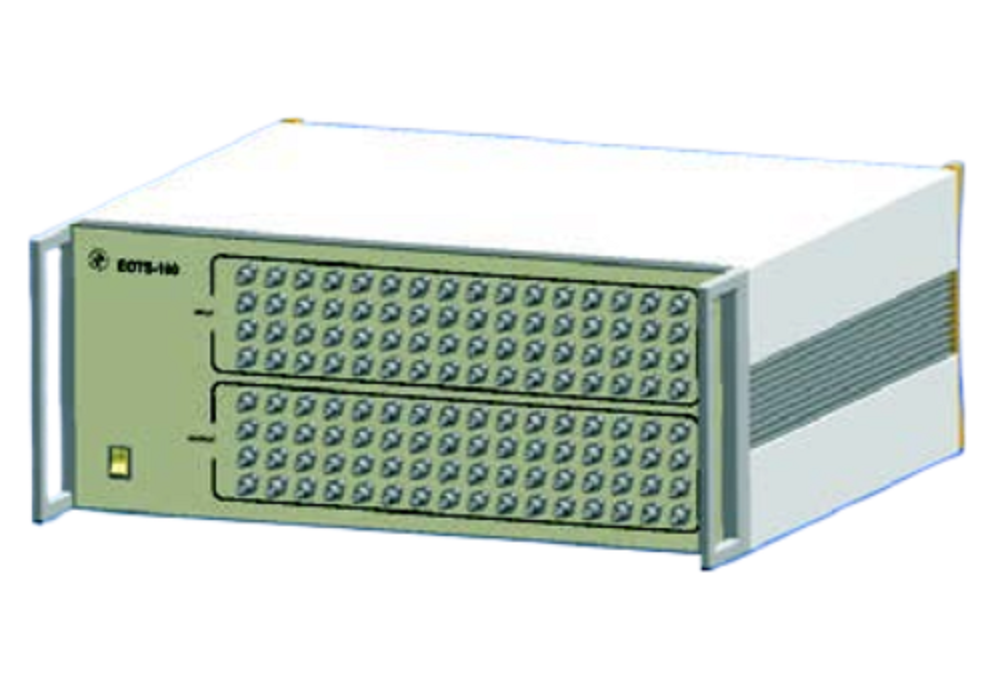
No. of Channels 12, 24; 1310, 1550, 1625 nm; Source Type SLED; Output Power Level >-6 dBm; IL Repeatability ±0.025 dB; IL Dynamic Range 50 dB; Fiber Type SMF-28; Connector Type Ultra FC/PC, FC/APC, SC, SCA, LC, MU OZ Optics has developed an environmental multi-channel optical test system allowing fast, simple and flexible long-term reliability testing. The system integrates an optimized optoelectronic design (including sources, optical switches, and photodetectors) and robust system management software. The EOTS-100 system allows optical manufacturers to perform automated and flexible long-term testing for compliance with industry standards such as Telcordia generic requirements (GR-326-CORE, GR-1209-CORE and GR-1221-CORE). The meter offers the capability of characterizing very low insertion loss (IL) drift. It also offers the optional capability of measuring return loss and polarization dependent loss variations. Measurement capability using tunable sources can also be offered The system can be run through any computer operating Windows™. The management software has a built-in database for data processing and statistical analysis of multiple sets of measurements. Collected data can be graphically displayed for easy interpretation. Remote configuration and operation of the unit is possible with the unit via a parallel printer port, a standard serial communication port (RS232) or General Purpose Interface Bus (GPIB). Key Features: Long-period Testing Capability for Optical Passive Component Reliability Multiple Wavelength Configurations Multiple Channel Configurations Optional Swept Wavelength Capability Flexible and Simple User Interface Statistical Measurement Analysis Custom Configuration Designs Available Optional Optical Return Loss (ORL) Capability Optional Polarization Dependent Loss (PDL) Measurement Capability Wavelength: 1310 nm, 1550 nm or 1625 nm Source Type: SLED Output Power Level: >-6 dBm Number of Channels: 12 or 24 Insertion Loss (IL) Repeatability: ±0.025 dB Insertion Loss (IL) Dynamic Range: 50 dB Optical Return Loss (ORL) Accuracy: ±0.5 dB up to 55 dB, ±1 dB from 55 dB to 60 dB (for FC/APC on DUT) Polarization Dependent Loss (PDL) Accuracy: ±(0.01 dB + 5% of PDL) PDL Dynamic Range: 0.025 dB up to 10 dB Fiber Type: SMF-28 (9/125/900 μm) Single Mode (SM) Fiber Input/Output Connector Type: Ultra FC/PC, FC/APC, SC, SCA, LC, or MU Display Resolution: 0.01 or 0.001 dB Switch Life Time: Over 10 Mio. Cycles Adjacent Channel Switching Time: 10 ms Host Computer Operating System: Windows 2000, Me, XP, 98. Min. Computer Requirements: 300 MHz or faster Pentium III Computer, 128 MB of RAM, External Control Parallel Printer Port, RS-232 or GPIB Input Voltage: 100 VAC to 240 VAC / 50 Hz to 60 Hz Operating Temperature: 0°C to +50°C Dimensions (Without External Computer : 17.6 x 48 x 36 cm (19 Inch Rack Mountable) Weight: <10 kg Applications: DWDM Channel Testing; Long-term Reliability Testing on Optical Passive Components; Characterization of Insertion Loss (IL) Versus Wavelength Dependence; Optical Return Loss (RL) Measurement; Characterization of PDL Dependence Versus Wavelength; Product Qualification as per Telcordia; Quality Control
REQUEST PRICING AND AVAILABILITY
- Get your individual quote.
- Technical compatibility review included.
- Volume discounts available.
No obligation. Direct access to our engineering team.

ER-100 Polarization Extinction Ratio Meters
Handheld Type; 400 to 2400 nm; Extinction Ratio Range 30, 35, 40 dB; Extinction Ratio Accuracy ±1 dB; Angular Accuracy ±0.5°; Adapter Type FC/PC, ST, E2000, SC, LC, MU, Universal 1.25/2.5 mm OZ Optics’ ER-100 series of polarization extinction ratio meters allows one to quickly measure the output extinction ratio of light from a fiber. A rotating polarizer measures the extinction ratio and the orientation of the transmission axis with respect to the key on the connector. As an option, neutral density filters can be added to the ER-100 extinction ratio meters to extend the maximum power range. These filters can be easily inserted and removed without disturbing your setup and allow power levels up to 2 W to be measured. The ER-100 meters operate in several modes. In real time mode, the meter gives the extinction ratio and alignment. In logging mode, the meter gives the worst-case extinction ratio over a given time span. This mode is ideal for QA measurements. In addition, the meter can provide a relative power readout, proportional to the input power in dB. This readout is updated at up to 650 times per second. The computer interface allows the unit to be used with computer control units, for alignment purposes. The combination of polarization and relative power functions allows the unit to be used for complete auto-alignment of polarization maintaining components. Key Features: Measures Extinction Ratio up to 40 dB (Over Specific Wavelength Ranges) Built-in USB Communications Interface Wide Wavelength Range: 400 to 1000 nm for Visible; 850 to 1650 nm and 1800 to 2400 nm for IR 0.01 dB Resolution in ER and 0.3° Resolution in Angle 1dB Accuracy in ER, 0.5° Accuracy in Angle Measures up to 2 W CW Input Power Rugged and Compact Design Logging Mode for Continuous Measurement Interchangeable Connector Adaptors Applications: Fiber Optic Component Manufacturing; Automated Alignment; Quality Control and Measurement; Product Development; Component or System Troubleshooting
REQUEST PRICING AND AVAILABILITY
- Get your individual quote.
- Technical compatibility review included.
- Volume discounts available.
No obligation. Direct access to our engineering team.

ER-1000 Polarization Extinction Ratio Meters
Benchtop Type; 450 to 2400 nm; Extinction Ratio Range 30, 35, 40 dB; Extinction Ratio Accuracy ±0.15, ±0.5 dB; Angular Accuracy ±0.5°; Adapter Type FC/PC, ST, E2000, SC, LC, MU, Universal 1.25/2.5 mm OZ Optics’ ER-1000 series of benchtop polarization extinction ratio meters allows one to quickly measure the output extinction ratio of light from a fiber. A rotating polarizer measures the extinction ratio (ER) and the orientation of the transmission axis with respect to the key on the connector. As an option, neutral density filters can be added to the ER-1000 extinction ratio meters to extend the maximum power range. These filters can be easily inserted and removed, without disturbing your setup and allow power levels up to 2 W to be measured. The ER-1000 meters operate in several modes. In real time mode, the meter gives the extinction ratio and alignment. In logging mode, the meter gives the worst-case extinction ratio over a given time span. This mode is ideal for QA measurements. In addition, the meter can provide a relative power readout, proportional to the input power in dB. This readout is updated at up to 650 times per second. The computer interface allows the unit to be used with computer control units, for alignment purposes. The combination of polarization and relative power functions allows the unit to be used for complete auto-alignment of polarization maintaining components. Key Features: Measures Extinction Ratio up to 50 dB (Over Specific Wavelength Ranges) Very Wide Wavelength Range: 450 to 900 nm for Visible; 850 to 1650 nm or 1800 to 2400 nm for IR ±0.15 dB ER Accuracy up to 30 dB, ±0.5° Accuracy in Angle 0.01 dB Resolution in ER and 0.3° Resolution in Angle Power Measurement up to 2 W Interchangeable Connector Adaptors Logging Mode for Continuous Measurement USB Communications Interface Touch Screen Display Built-in Memory for Store and Recall Functions Applications: Fiber Optic Component Manufacturing and Testing; PMC and PBS PER and Coupling Ratio Testing; PM Fiber Laser Diode Pigtailing; PM Fiber Patch Cord Production and Testing; PM Fiber Fusion Splice Testing; Automatic Alignment; Quality Control and Measurement; Product Development; Component and System Troubleshooting
REQUEST PRICING AND AVAILABILITY
- Get your individual quote.
- Technical compatibility review included.
- Volume discounts available.
No obligation. Direct access to our engineering team.

FOFF-100 Fiber Optic Fault Finder
1310, 1550 nm; Sampling Resolution 2.5 m; Dead Zone 10, 40 m; Max. Measurement Distance 25, 60 km; Fiber Type 9/125 µm SM, Other OZ Optics’ FOFF Fiber Optic Fault Finder is a cost effective, easy-to-use, OTDR-type device that provides continuous monitoring of fiber optic network health. The device detects and pinpoints bad connections, fiber bends, broken fibers and other problems that can lead to reduced network performance or service failure. The fiber optic fault finder combines powerful fault detection and communications capabilities in a compact package. Remote access capability allows secure monitoring of network operating conditions using a computer from virtually anywhere. The OZ FOFF fiber optic fault finder can be bundled with an optional software package capable of gathering raw fault location data, transforming that data into actionable information, and serving it up via text message, email, instant message, and the web. Escalating alarms, starting with the field engineer, and rising to any level specified by the network operator, are a standard feature of the software. The software is available as a hosted web service or for integration into customer NOCs. The device enables fiber optic network operators to increase field engineer efficiency, improve network and service availability and achieve a higher overall return on investment (ROI) from fiber optic networks. Networks suitable for monitoring by the FOFF fiber optic fault finder include FTTX access networks, backbone and metro transport networks, enterprise fiber networks, and multi-service operator (MSO) networks including hybrid fiber/coax (HFC) networks. Key Features: Compact System Monitors and Reports Network Health Status in Real Time 24 h/day, 365 days/year Reduces Revenue Loss Due to Damaged Fiber Reports Fault Location With Time Stamp Escalates Faults to Tiered Operational Support System Lowers Network Operating and Maintenance Expenses Improves Network and Services Availability User Friendly Interface Via USB, RS-232, or Ethernet Cellular Phone, Email, IM, SMS, Text Message for Outages or Early Alert Reporting Wavelength: 1310 nm or 1550 nm, Other Wavelengths Also Available Fiber Type: 9/125 µm Single Mode (SM), Other Fiber Types Also Available Optical Connector: FC/APC, Other Connector Types Available Dead Zone: 10 m to a Reflective Event, 40 m to a Non-reflective Event; Smaller Dead Zones Also Available Sampling Resolution: 2.5 m, Better Resolutions Also Available Distance Accuracy: 5 m + (3x10⁻⁵ x Distance) – Does not Include Errors From Index of Refraction Maximum Measurement Distance (Using a 50 ns Pulse): 60 km (Reflective Event), 25 km (Non-reflective Event) – Longer Distances Also Available Power Supply: 12 VDC to 15 VDC, 500 mA (Max.) Applications: Network Fiber Infrastructure Health Monitoring and Fault Reporting; Backbone and Metro Transport Network Monitoring; FTTX Access Network Monitoring; MSO HFC Networks; Enterprise, Private, Campus Fiber Network Monitoring; Mission Critical Fiber Link Monitoring; Performance Monitoring Subsystem for Protection Switch or Route Diversity; Field Technician Test and Troubleshooting Tool for Access or Building Network; Real Time Inline Test and Measurement; Fiber Network Long-term Performance Data Collection and Analysis
REQUEST PRICING AND AVAILABILITY
- Get your individual quote.
- Technical compatibility review included.
- Volume discounts available.
No obligation. Direct access to our engineering team.

KI 23400 & KI 27400 Handheld Two-Way Loss/Length/ORL Test Set
635-1650 nm; Loss Range 21.5-44 dB; Loss Repeatability/Linearity 0.04, 0.06 dB; Power Accuracy 1% Kingfisher’s KI 23400 & KI 27400 is an optical, handheld, two-way loss test set (OLTS) with length and ORL measurement that is perfect for ultra-high fiber count tier 1 loss & length testing applications. A pair of these compact instruments set new standards of productivity, accuracy and ease of use. Each fiber needs just one test hook-up and one key press for a complete bidirectional loss, length and ORL test, for both single mode (SM) and multi mode (MM) fiber, so the same test method can be used for all fibers in a network, eliminating administration, training and test errors. Testing is accurate and can take only five seconds, direct onto a final report. The “Visitester” option lights up the far end of the fiber to be tested. A pair of KI 23400 & KI 27400 instruments both display length as well as bi-directional loss and ORL each end, in one hook-up, in real time, with no need to specify master/slave instruments. A single instrument can also be used as a stand-alone light source & power meter, ORL meter, VFL, or tone generator/detector. Key Features: Ease to Use, Slim & Versatile Loss, Length & ORL Tester for High Fiber Counts 25% of the Size/Weight, 7x the Battery Life of Competitors Alkaline Battery Life: 80 h USB External Power EF Compliant Multi Mode Sources Single Mode (SM), Multi Mode (MM), Quad & Other Wavelengths Wavelength Range 635 to 1650 nm Loss Range: 21.5 to 44 dB Loss Repeatability / Linearity: 0.04, 0.06 dB Bidirectional Autotest Loss, ORL & Length Testing on One Fiber Real-time Pass/Fail Display Interchangeable Connectors 8,000 Fiber Memory and USB Interface KITS™ Reporting Software Autotest Power Meter Power Accuracy: 1% 24 Calibrated Wavelengths Continuity Test Tone With Multi-Fiber ID VFL VisiTester Option ISO 17025 Traceable Full QA & Test Reports for Source Stability / λ, & Power Meter Linearity Dimensions: 190 x 105 x 35 mm Weight: 420 g 3 Year Warranty and Calibration Cycle Applications: Single Mode (SM), Multi Mode (MM) & Both Fiber Types; Tier 1 Cable Certification & Reporting; Bidirectional Loss, Length & ORL in One Hook-up With Integrated VFL (VisiTester); Optical Power, Continuity & Polarity
REQUEST PRICING AND AVAILABILITY
- Get your individual quote.
- Technical compatibility review included.
- Volume discounts available.
No obligation. Direct access to our engineering team.

KI 6171 Optical Fiber Identifier
Fiber Type SM; Wavelength Detection 800-1700 nm; Test Tones 0.27, 1, 2 kHz; IL 0.8, 2.5 dB; Power Detection Range -50-+10 dBm Kingfisher’s KI 6171 tone and traffic identifier is a rugged, easy to use instrument used to identify optical test tones, live traffic and optical power levels in single mode (SM) fiber. KI 6171 optical fiber identifiers are commonly used during installation and maintenance of fiber optic systems to positively identify fibers to avoid accidently disconnecting live systems, and for general checking of continuity, faults or mid-span loss points. The KI 6171 optical fiber identifier is easy and reliable to use with one hand. It can detect a variety of optical tones, which can be provided by any Kingfisher laser source. When traffic is present, an audible tone can be heard as well as LED indication of traffic direction and estimated core power. Various field interchangeable chucks are supplied and enable rapid re-configuration for a variety of fiber cord diameters. Chucks not in used are securely stored and conveniently carried along with the equipment in the slide-on compartment hence reducing chances of those chucks being misplaced. The approximate core power in the fiber is measured and displayed on a two-digit display. Its very long distance operating range of up to 200 km makes the KI 6171 optical fiber identifier suitable for use where a VFL cannot reach. Key Features: Single-handed Operation Very Easy to Operate Thumb Lock for Consistency & Hands-free Operation Wavelength Detection: 800 to 1700 nm Identifies and Displays Dominant Traffic Direction With Audible Alert Identifies 3 Common Test Tones: 270 Hz, 1 kHz, 2 kHz Low False Detection Low Insertion Loss (Typical): 0.8 dB (1310 nm), 2.5 dB (1550 nm) Approximate Fiber Power Meter Display Power Detection Range: -50 to +10 dBm (CW in 0.9 mm Bare Fiber) Supplied With 4 Easy-change Heads for Ribbon / 250 μm Coated Fiber, 900 μm Fiber, 2 mm & 3 mm Patch Lead Slide-on Compartment for Chuck Storage Fiber Slack: 12 mm Uses 2 x AAA Alkaline Batteries Auto On/Off Durable Metal Housing and Quality Construction Dimensions: 196 x 30.5 x 27 mm Weight: 200 g 1-year Warranty Full QA Report Applications: Positive Identification of Fibers Carrying Traffic or a Test Tone; Approximate Indication
REQUEST PRICING AND AVAILABILITY
- Get your individual quote.
- Technical compatibility review included.
- Volume discounts available.
No obligation. Direct access to our engineering team.

KI 7010 Series Variable Optical Attenuators
Digital Variable Handheld Attenuator; Fiber Type SM, MM, POF; 650-1550 nm; Attenuation Range 2.0-60 dB; Resolution 0.05 dB; RL 60 dB Kingfisher’s KI 7010 Series of handheld fiber optic variable attenuators are precision instruments commonly used for testing optical system margin, linearity and sensitivity of optical transmission equipment and to adjust a source output power. Superior specifications, superb accuracy, high productivity and numerous useful attributes like remote-control capability make the KI 7010 Series genuine laboratory grade instruments. Versions are available for single mode (SM), multi mode (MM) and POF fiber types. Very flat wavelength response enables confident testing of CWDM/DWDM systems. The instrument wavelength setting is actually irrelevant in most situations up to about 20 dB of attenuation. Industry leading linearity and absolute accuracy backed up by an ILAC / ISO 17025 traceable calibration certificate enable precision linearity testing of sub systems and components. Full absolute calibration is performed at all wavelengths and attenuation values. The patented metal-free interchangeable connectors avoid critical contamination of connectors used in high power applications. Operational modes include manual, relative, step and remote control via a PC. Step mode is very useful for typical linearity checking applications. The free Labwindows-based PC software is used to provide external control. External control is provided via an RS232 interface. Alternatively, a simple command set can be used to program the instrument using your own code. The attenuation remains stable as the instrument is turned on or off, making the device suitable for embedded use in working systems. Power can be supplied externally. Key Features: Compact, Rugged & Light Weight Single Mode (SM), Multi Mode (MM) & POF Versions Easy to Use, Accurate & Productive Instruments Excellent Linearity and Absolute Loss Accuracy Wavelength Range: 650 to 1550 nm Up to 2 Calibrated Wavelengths Attenuation Range: 2.0 to 60 dB Resolution: 0.05 dB Optical Return Loss (RL): 60 dB Polarization Dependent Loss (PDL): <0.1 dB Polarization Mode Dispersion (PMD): <1 ps ISO 17025 Traceable Calibration Certificate High Optical Power Handling Capability: up to >+30 dBm / 1,000 mW Broadband, Flat Wavelength Response Low Minimum Insertion Loss Supplied With Metal-free SC, ST, LC Interchangeable Connectors Multiple User-defined Sequences Remote-control (Labwindows) Software Set Attenuation is Unaffected by Power On/Off Status Very Long Battery Life & External Power 3 Years Warranty Applications: Testing Optical Transmission Equipment, Field, Handheld, Bench, Embedded; Optical Margin Testing; Sensitivity Testing; Linearity Testing; Source Output Power Adjustment; Temporary Passive Adjustable Transmission Pad
REQUEST PRICING AND AVAILABILITY
- Get your individual quote.
- Technical compatibility review included.
- Volume discounts available.
No obligation. Direct access to our engineering team.

KONCENTRIK-V2 CONNECTOR Concentricity Measurement System
Eccentricity Range 0 to 100 µm; Index Measurement 0° to 360°; Measurement Speed 10 s; Magnification x400; Ferrule Outside Diameter 1.00 to 3.17 mm Data-Pixel’s KONZENTRIK-V2 is a modular measurement system. Fiber or ferrule eccentricity measurements can be performed using different mechanical modules. KONZENTRIK-V2 CONNECTOR is dedicated to concentricity measurement of fiber core relative to ferrule envelope. The unit is able to measure the concentricity and indicate the angular value of maximum eccentricity. With the BLINK software platform, KONZENTRIK-V2 CONNECTOR is an easy to use measurement unit with database connectivity. KONZENTRIK-V2 CONNECTOR systems are compatible with Data-Pixel’s SUPERVISOR software, a MES style software which is in charge of the execution, management and monitoring of the production in an assembly workshop for fiber optic connectors. Its role is to supervise machines and help operators with complete traceability of the manufacturing information. Key Features: Measures Diameter 2.50 and 1.25 mm PC Type Connectors APC Connectors Option Available Ferrule End-face Visual Inspection at x400 Magnification Accurate and Repeatable Measurements User Adjustable Quality Level for High-speed Measurements Easy Calibration BLINK Concentricity Software Measurement Data Exported in Standard CSV Format Statistics on Measurements Available Measurement Report in HTML Format Compatible With Desktop PC, Laptop, Tablet PC Applications: Measurement of Connector Eccentricity; Concentricity Measurement of Fiber Core Relative to Ferrule Envelope; Indicate Angular Value of Maximum Eccentricity
REQUEST PRICING AND AVAILABILITY
- Get your individual quote.
- Technical compatibility review included.
- Volume discounts available.
No obligation. Direct access to our engineering team.

KONCENTRIK-V2 FERRULE Concentricity Measurement System
Eccentricity Range 0 to 100 µm; Index Measurement 0° to 360°; Measurement Speed 3 s; Magnification x400; Ferrule Outside Diameter 1.00 to 3.17 mm Data-Pixel’s KONZENTRIK-V2 is a modular measurement system. Fiber or ferrule eccentricity measurements can be performed using different mechanical modules. KONZENTRIK-V2 FERRULE is dedicated to concentricity measurement of ferrule bore to ferrule envelope. The software indicates the maximum eccentricity angle when rotating the ferrule. With the BLINK software platform, KONZENTRIK-V2 FERRULE is an easy to use measurement unit with database connectivity. KONZENTRIK-V2 FERRULE systems are compatible with Data-Pixel’s SUPERVISOR software, a MES style software which is in charge of the execution, management and monitoring of the production in an assembly workshop for fiber optic connectors. Its role is to supervise machines and help operators with complete traceability of the manufacturing information. Key Features: Measures Ceramic and Metal PC-type Ferrule Automatic Measurement and Re-positioning of Ferrule at Tuned Position Ferrule End-face Visual Inspection at x400 Magnification Ferrule Envelope on Bare Ferrules & Bore Shape-error Measurement User Adjustable Quality Level for High-speed Measurements Easy Calibration BLINK Concentricity Software Measurement Data Exported in Standard CSV Format Statistics on Measurements Available Measurement Report in HTML Format Compatible With Desktop PC, Laptop, Tablet PC Applications: Measurement of Ferrule Eccentricity; Concentricity Measurement of Ferrule Bore to Ferrule Envelope
REQUEST PRICING AND AVAILABILITY
- Get your individual quote.
- Technical compatibility review included.
- Volume discounts available.
No obligation. Direct access to our engineering team.

MAP-220C Optical Application Mainframes
Capacity 2 Cassettes; 3.5-in Color Touch Screen; Interfaces USB, Ethernet, GPIB (optional); Operating System Linux; Driver IVI compliant Viavi Solutions’ MAP-220C series of two-slot modular chassis provides a compact footprint lab and manufacturing test solution supporting optical test switching and signal conditioning in optical device and sub-system development and manufacturing. MAP-220C is available in three main configurations (benchtop, rack-mount and reverse rack-mount) that simplify lab use or manufacturing test station integration. With its configuration flexibility, such as horizontal or vertical placement, front or rear test access, and side-by-side 19 inch rackability, the MAP-220C series supports Viavi Solutions’ family of LightDirect modules. The compact, 2U, two-slot MAP-220C chassis mainframe is designed for general fiber-optic lab use and smaller optical manufacturer test-station deployments. MAP-220C is as efficient and cost-effective as fixed-format versions yet maintains the flexibility and modularity so you can build the application you want, when you want. The MAP-220C series hosts a specific subset of the broader MAP-300 module array focused on light sources, power meters, switches, and attenuators. These basic foundational modules serve as the key building blocks for most test applications. Users can leverage these modules in a compact, benchtop format with a simple, intuitive graphical touch screen. For larger, more complex deployments, Viavi Solutions recommends the MAP-330 (three-slot) and MAP-380 (eight-slot) chassis systems. These chassis support all released MAP-300/200 modules. All MAP modules and chassis are completely interoperable with remote interface (GPIB or LXI). Key Features: Compact, Two-slot Benchtop Configuration Local Hi-visibility Capacitive Touch Screen Interface GUI Backward Compatible to Legacy SB & SC Switches Front or Rear Test Access to Optical Interfaces Horizontal or Vertical Chassis Placement on Bench or in Rack LXI-compliant Interface With Optional GPIB Interfaces Include GPIB, RJ45 Ethernet Pop-up Front and Rear Feet With Bumpers for Stacking Field-replaceable Controller/Power-supply Module Applications: Lab Research & Development of Active Optical Devices (e.g. Transponders, Amplifiers, Line Cards); Manufacturing of Active Optical Devices; General Purpose Optical Test Switching (e.g. Passive or Active Optical Device Work); General Purpose Fiber-optic Lab Use; Manufacturing Test Automation; Light Source and Optical Power Meter Deployment; Optical Switch and Attenuator Deployment
REQUEST PRICING AND AVAILABILITY
- Get your individual quote.
- Technical compatibility review included.
- Volume discounts available.
No obligation. Direct access to our engineering team.
MAP-300 Optical Application Mainframes
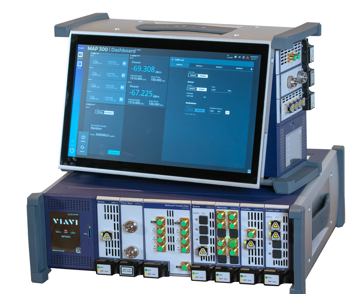
Capacity 3, 8 Cassettes; 3.5-in Touch Screen; Interfaces USB 3.0, Ethernet, Monitor Port; Operating System Linux; Optical Plug-in Modules GPIB, USB/LAN Expansion, Trigger Viavi Solutions’ MAP-300 series of multiple application optical test and measurement platform is optimized for compact cost-effective development and manufacturing of optical communications technology. The MAP system is the heart of Viavi Solutions’ optical test solutions for labs and manufacturing. With unmatched scalability, users can be assured that these solutions will meet their current and future needs. MAP-300 provides the foundation to Viavi Solutions’ entire portfolio, enabling scalability and efficiency for manufacturing optical network elements, modules and components. The MAP-300 series is compatible with all Viavi Solutions’ current cassettes and legacy cassette (all -C1, -C2 and -B1 modules). The cassette modules fall into two different families, the LightTest turn-key solutions and LightDirect configurable solutions to meet each customer’s exact needs. While the LightDirect family of easy-to-control, single-functionality modules includes a wide range of foundational optical test modules that are used in simple bench test applications, or combined in larger, multi-modules customer driven automated test systems, the LightTest family are application specific, integrated test solutions that leverage the power of the MAP Series Super-Application or PC based software. MAP-300 builds upon the proven strengths of the MAP System while adding innovation where it matters most for our customers. Backwards compatible support for the installed automation base, combined with several new features, including an HTML-based GUI for multi-user environments, gives customers the capabilities they need to achieve their goals. The MAP-300 mainframe, like its predecessor, is offered in both benchtop and rackmount versions as either three (MAP-330) or eight slot (MAP-380) mainframe configurations. The eight-slot version can also be provided in a reverse rack-mount configuration. Key Features: Rackmount, Reverse-rackmount and Benchtop Mainframe Configurations HTML-based Graphical User Interface for Consistent User Experience Locally & Remotely Field-replaceable Controller Includes an Integrated 3.5-inch LCD Touchscreen Support for USB 3.0 Port, 15.6-inch External Monitor and Ethernet Optional GPIB, Additional Ethernet Ports and Additional USB and Trigger Modules SCPI Logical Interface for Automation Programming with Remote Programming Supported Multi-user Capabilit Backward Compatible with MAP2xx Series Cassettes and Remote-control Support Hot-swappable Modules Applications: General Purpose Fiber-optic Lab Use; Manufacturing Test Automation; DWDM/WSS Test; Connectivity IL/RL; Polarization Scrambling and OSNR
REQUEST PRICING AND AVAILABILITY
- Get your individual quote.
- Technical compatibility review included.
- Volume discounts available.
No obligation. Direct access to our engineering team.

mEDFA-C1 MAP Benchtop EDFA Modules
Erbium-doped; 1528 to 1610 nm; Input Power -4 to 0 dBm; Output Power ≥20, ≥21, ≥25 dBm Viavi Solutions’ mEDFA-C1 series of MAP Erbium Doped Fiber Amplifiers meets some of the most demanding optical specifications including a low-noise version with <3.7dB noise figure. DWDM, high power and an L-band version are also available. mEDFA-C1 MAP is a third-generation amplifier design, optimized for use in the systems lab or for optical test and measurement applications. The simplified control and modular design make the module extremely simple to integrate and use. It removes the need to “work-around” networking management protocols that often frustrate R&D and manufacturing engineers and slow down test automation. The mEDFA-C1 has six carefully selected variants designed to span the most critical application requirements. While simple to control from the front panel or over the remote interface, the mEDFA-C1 MAP amplifiers meet some of the most demanding optical specifications including a low noise version with <3.7dB noise figure. These low noise amplifiers are essential for test automation implementations where system path loss requires a test signal power boost prior to application to the DUT. In most cases OSNR impairments must be kept to a minimum. Auto gain and power control options are designed to simplify power management, in particular when a single channel tunable source is used. DWDM, High Power and an L-band version are also available. As part of the MAP-300 family (also compatible with MAP-200), the mEDFA-C1 MAP module series is an Ethernet or GPIB modular instrument that can be directly managed from your PC-based automation system. A member of the LightDirect Family of MAP-300 modules, the mEDFA-C1 can be deployed in the compact MAP-220C 2-slot chassis, the MAP-330 3-slot chassis or the larger MAP-380 8-slot chassis systems. Alongside the many other modules, such as amplifiers, precision attenuators, power meters and spectrum analyzers, MAP-300 is the ideal modular photonics test platform for 100G+ test applications. Key Features: Variant Options to Cover Low Noise Figure (<3.7 dB) or High Power (>25 dBm) Requirements Single-channel Extended C and L Band Versions Gain Flattened DWDM Multichannel Extended C Band Versions Automated Gain and Power Control Options Applications: Amplification of Sensitive Signals in Automated Test Systems; Power Saturation Recovery Testing; OSNR Noise Loading
REQUEST PRICING AND AVAILABILITY
- Get your individual quote.
- Technical compatibility review included.
- Volume discounts available.
No obligation. Direct access to our engineering team.

mHROSA-A1 MAP Optical Spectrum Analyzers
1527 to 1568 nm; Fiber Type Single Mode; Connector Type FC/APC; Accuracy ±370 MHz; Max. Input Power +17 dBm Viavi Solutions’ mHROSA-A1 MAP series of MAP-based integrated multi-wavelength meters and high resolution OSA modules combines sub-GHz resolution performance and compact modularity in a single-slot cassette. Supported in MAP-300 (and legacy MAP-200) mainframes, mHROSA-A1 MAP can take advantage of the wide array of other Viavi MAP modules such as power meters, attenuators, switches, sources and a range of signal conditioning modules. The mHROSA-A1 MAP series consist of richly featured multi-wavelength meters and high-resolution OSAs with analysis features that can be controlled through an easy-to-use GUI or the MAP-300 automation interface. Based on coherent detection techniques, mHROSA-A1 MAP has no moving parts and it provides unprecedented frequency resolution to precisely report the power level and central frequencies of densely spaced optical signals as close as 2 GHz. The ground-breaking mHROSA-A1 MAP series provides the ideal solution for both lab and manufacturing test systems, where reliability, compactness, and performance are critical. In combination with Viavi Solutions’ mWAVE-A1 MAP series, these modules are ideal for automated test in manufacturing environments. Based on coherent detection technology, they provide unprecedented frequency resolution to precisely report the power level and central frequencies of densely spaced optical signals as close as 2 GHz. This combination is the ideal solution for both lab and manufacturing test systems where reliability, compactness and performance are critical. Key Features: Sub-GHz Wavelength Resolution Extended C-band Acquisition Range Measures Frequency, Power Level and OSNR Continuous and Averaging Test Modes Measures Side-mode Suppression Ratio Applications: DWDM Transmission Systems; Optical Sources; Transponders and Linecards; Qualify 10/40/100/400 G Components and Systems; Validate and Deploy 100 G and 400 G Flex-grid DWDM
REQUEST PRICING AND AVAILABILITY
- Get your individual quote.
- Technical compatibility review included.
- Volume discounts available.
No obligation. Direct access to our engineering team.

mORL-A1/mIL-A2 MAP Benchtop IL and RL Test Solutions
2 and 4 wavelengths versions; 850 to 1625 nm; Measurement Time Averaging Options 2, 5, 10 s; Fiber Type Single Mode, Multi Mode; Connectors FC/APC, FC/PC Viavi Solutions’ mORL-A1/mIL-A2 MAP series provides single mode insertion loss / return loss test meters and fully EF-compliant multi mode insertion loss test modules for use with Viavi Solutions’ advanced MAP-300 (and legacy MAP-200) platforms. Viavi Solutions’ passive component/connector test solution (PCT) consists of a powerful family of modules, software and peripherals for testing insertion loss, return loss, physical length, and polarity of optical connectivity products. Leveraging the modularity and connectivity of Viavi Solutions’ MAP-300 (and legacy MAP-200) platform, the PCT can be configured for R&D, production, or qualification test environments and can address all key fiber types from single mode through OM1 and OM4. The mORL-A1/mIL-A2 MAP series is often used in conjunction with the optical switch (mOSW-C1/mISW-C1) and remote optical power meter (mOPM-C1) MAP modules. In mORL-A1 MAP series single mode IL and RL meters, one single-slot module contains up to four sources (1310, 1490, 1550, 1625 nm), and integrated power meter, and an optional 2x2 optical switch for automated bidirectional testing. mORL-A1 MAP series multi mode IL and RL modules are based on the same basic technology and architecture as the single mode modules described above. A standard dual-wavelength version is available (850, 1300 nm) for multi mode applications with an integrated power meter and optional 2x2 optical switches for automated bidirectional testing. The dual-fiber option can test 50 µm or 62.5 µm from the same module. The final measurement module in the PCT family is the mIL-A2 MAP multi mode insertion loss meter which is a powerful, stable, and compact IL-only solution. One single-slot module contains two LED sources (850 nm and 1300 nm) and an integrated power meter for manual or automated testing. It is an ideal lower-cost option for applications that do not require RL measurements. Its excellent source stability and launch monitoring minimizes reference frequency requirements. The MAP-300 (and legacy MAP-200) series is the first photonic layer lab and manufacturing platform to be LAN Extensions for Instrumentation (LXI)-compliant, bringing the full power of Ethernet connectivity and ease of use of interchangeable virtual instrument (IVI) drivers to the optical test environment. The MAP Series platform’s industry-leading density and configurability enables test engineers to meet specific application requirements in the smallest possible footprint. Key Features: Increases Production Yield by a Factor of 4 Requires Only 25% of the Space of Other Solutions Enables Expansion Into New High-growth, High-performance Applications such as 40/100 G Data Center Markets Modular Platform Can Scale as Needs Arise and Budget Allows Port Mapping Verifies Multifiber MPO Cassette Continuity and Polarity in Less Than 15 Seconds Fully Supports High-growth MPO and MTP Multifiber Connectors Applications: Testing IL/RL/Length of Optical Connectors and Cable Assemblies, Structured Cabling Solutions and Optical Splitters; Automated Test of Multifiber Assemblies such as MPO; Solutions for Both Single Mode and Multi Mode Fiber-based Devices; Verifying Continuity and Polarity of Large Multifiber Assemblies; Measuring RL of Line Cards and Receptacle-based Transponders
REQUEST PRICING AND AVAILABILITY
- Get your individual quote.
- Technical compatibility review included.
- Volume discounts available.
No obligation. Direct access to our engineering team.
mOSW-C1/mISW-C1 MAP Benchtop Optical Switch Modules
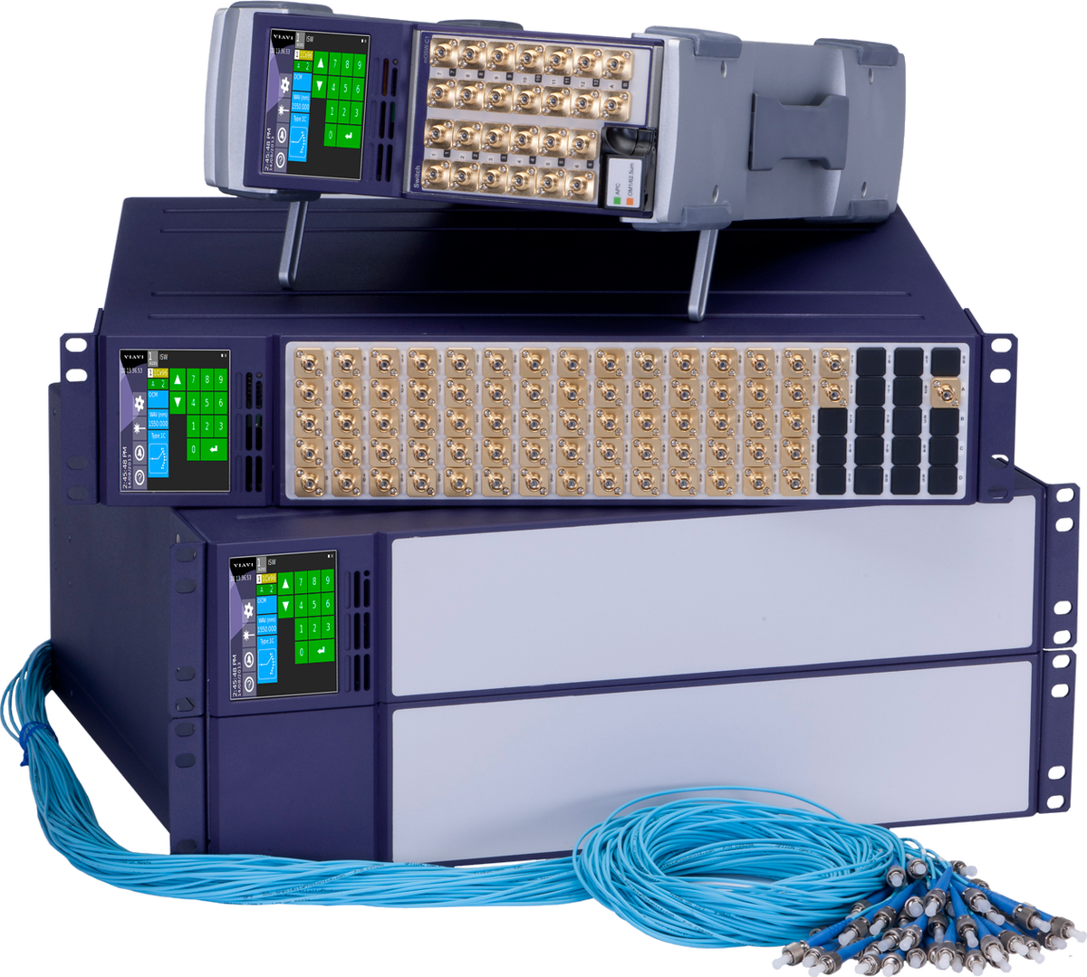
Module & Tray Versions; 760 to 1650 nm; Insertion Loss 0.7 to 1.2 dB; Return Loss 25 to 62 dB; max. Crosstalk -55, -60, -80 dB; Max. Input Power 300 mW Manufacturing test automation is critical to reducing product costs and optical switches are at the heart of any automated test system. Viavi Solutions’ mOSW-C1 MAP series of optical switch modules and mISW-C1 MAP series of optical switch trays are built on the industry-leading, fourth-generation instrumentation class of Viavi Solutions optical switch technology. With more than 30 years of leadership in optical switching across network, monitoring, and manufacturing applications, the mOSW-C1/mISW-C1 MAP series represents a new milestone for performance and reliability with the industry’s smallest footprint. For the first time, the performance and repeatability found in large, fixed format 19-inch Viavi Solutions rack-mount systems are available in a modular plug-in or tray. Manufacturing engineers no longer have to choose between test system’s size and its performance. Leveraging the mOSW-C1/mISW-C1 MAP series can reduce the size of switching systems by as much as 75% while still delivering the performance of much larger legacy systems. A 50% increase in switching speeds significantly saves testing time for connection-intensive architectures. These switches are components of the MAP-300 (and legacy MAP-200) family. With the widest range of optical modules in the industry, it is the most popular choice for manufacturing test automation across all optical industry segments. This includes the manufacture of passive components, transponders, and line cards. Advanced connectivity through remote VNC, Ethernet, GPIB, or local GUI makes the MAP-300 a natural choice for complex automation architectures because it dramatically simplifies debugging for remotely located manufacturing sites. Key Features: Provides All Optical Switching, Independently From Data Rate and Transmission Format Minimal Impact on Dynamic Measurement Range Regardless of Switch Size Low Loss for All Configurations from 1x2 to 1x176 Flexible SCPI Remote Interface Ultra-low 0.04 dB PDL and ±0.005 dB Repeatability New PTRIM Option Simplifies Troubleshooting and Measures In-line Power up to 20 dB- 1C, 2D (Duplex), and 2E Input Configurations Expanded Beam Technology Ensures Multi Mode Switches Are “Modally Transparent” Applications: Test System Automation for Multi-port Components, Modules and Line Cards; Management of Complex Test Sequencing in Manufacturing; Test of Multi-fiber Connectors (Paired With mORL-A1); Test for Long-term Reliability
REQUEST PRICING AND AVAILABILITY
- Get your individual quote.
- Technical compatibility review included.
- Volume discounts available.
No obligation. Direct access to our engineering team.

mPCX-C1 MAP Benchtop Fiber Polarization Controllers
Scrambling Modes Random, Rayleigh, Ring, Discrete; 1520 to 1620 nm; Max. Input Power 20 dBm; Insertion Loss <3 dB; Return Loss >40 dB Viavi Solutions’ mPCX-C1 MAP series of Multiple Application Platform (MAP) polarization scrambler controllers provides polarization scrambling, control and stabilization for use in applications such as temporal depolarization, 100G+ coherent interface testing as well as stabilization and tracking of target SOP conditions. mPCX-C1 MAP is a single-slot, high-speed polarization scrambler, controller and stabilizer. Based on Lithium-Niobate, the electro-optic waveplates have the response time required by the most demanding polarization management applications. With the rise of coherent modulation formats and polarization multiplex systems, there is a new premium on understanding the way the polarization state of these signals interacts with single mode fiber. The MPCX-C1 MAP is designed to enable these tests, not only in the laboratory, but also in the transition of these tests into a manufacturing environment. At its core, the mPCX-C1 MAP series cascades eight quarter wave-plates; each calibrated over the C+L band. These wave-plates can be rotated at high speed and are reset-free (endlessly rotatable) to control the state of polarization (SOP). Simple, predefined, rate-programmable, and polarization scrambling modes are provided which can achieve rates up to 3 Mrad/s. Alternatively, user-defined tables can be uploaded for custom scrambling patterns. With the proprietary SOP feedback option, two features are unlocked. The first enables an identified state to hold while the mPCX-C1 counteracts normal environmental drift and the second simplifies the automatic generation of unique diagnostic scrambling modes. As part of the MAP-300 family (also compatible with MAP-200), the mPCX-C1 MAP module series is an Ethernet or GPIB modular instrument that can be directly managed from your PC-based automation system. A member of the LightDirect Family of MAP-300 modules, the mPCX-C1 MAP can be deployed in the compact MAP-220C 2-slot chassis, the MAP-330 3-slot chassis or the larger MAP-380 8-slot chassis systems. Alongside the many other modules, such as amplifiers, precision attenuators, power meters and spectrum analyzers, MAP-300 is the ideal modular photonics test platform for 100G+ test applications. Key Features: High-speed Polarization Scrambler Rate Programmable rom 1.00 rad/s to 3.00 Mrad/s Operation in C+L Band With Less Than 3 dB of Insertion Loss Uniform Scrambling by Design, Independent of Input State of Polarization Six Advanced Scrambling Modes Including Rayleigh, Random and Ring Polarization Stabilization and Return-to-state Capability with Proprietary SOP Feedback Option Manual Polarization Control via Classic Waveplates Applications: Photonic Communication Test Automation; 100G+ Coherent Interface Testing; Temporal Depolarizer for Loss, Gain and PDL Min/Max Measurements; Stabilization and Tracking of Target SOP
REQUEST PRICING AND AVAILABILITY
- Get your individual quote.
- Technical compatibility review included.
- Volume discounts available.
No obligation. Direct access to our engineering team.

mTFX-C1 MAP Benchtop Tunable Filter Modules
120 Independent Filters; 1528 to 1610 nm; 2, 4, 8 Active Output Ports; Insertion Loss <5.5, <6.0, <6.5 dB; Return Loss >30 dB; Max. Input Power 9 to 24 dBm Viavi Solutions’ mTFX-C1 MAP series of Multiple Application Platform (MAP) multiport tunable filter modules dramatically simplifies test signal management for next-generation 100 G+ interfaces, sub-systems, and system test. The mTFX-C1 MAP series is a modular Ethernet or GPIB instrument and can be directly managed from your PC-based automation system. It eliminates the need to re-purpose optical network technology or use complex libraries with specialized interface cards. Based on next-generation liquid crystal on silicon (LCOS) technology, the mTFX-C1 MAP series is much more than a tunable filter. It combines variable attenuator, switch, power meter, and DWDM multiplexer functions to dramatically simplify photonic testing of coherent interfaces, amplifier, and DWDM systems. Leveraging TrueFlex™ technology, filters are continuously tunable in center wavelength and bandwidth and are not locked to the ITU grid. Multiple parallel wavelength paths can be created without disrupting already established connections—all with sub-GHz resolution. Industry-leading specifications for loss and out-of-band rejection ensure minimal impairments on your test signals. Using the mTFX-C1 MAP series, get the right wavelengths to the right test port with the right power—quickly – and flexibly isolate, groom, manage, and route any wavelength or group of wavelengths with a simple, intuitive GUI and/or SCPI-based remote commands. Key Features: Tunable Filter With Bandwidth Adjustment from 6.2 to 5100 GHz With 0.5 GHz Resolution Low Loss Continuous Extended C-band or L-band Coverage With ±3.5 GHz Wavelength Accuracy Up to 120 Independent Filters, Each With Independent Attenuation and Output Port Assignment New Filters Can Be Added and Removed Without Disturbing Existing Connections Internal Power Meter Option With Automated Single and Multiple Peak Find Algorithms Automated Peak Tracking Function Without Loss of Transmitted Power Fast, Simple GUI and SCPI Control Interfaces for Filter Generation Optional SW License to Enable up to 8 Output Ports Applications: Photonic Communication Test Automation; 100 G+ Coherent Interface Testing; ROADM Node Emulation; Signal Extraction or Insertion During DWDM System Testing; Amplifier Gain Spectrum Management and Load Tone Generation
REQUEST PRICING AND AVAILABILITY
- Get your individual quote.
- Technical compatibility review included.
- Volume discounts available.
No obligation. Direct access to our engineering team.

mUTL-C1 MAP Benchtop Passive Optical Modules
Passive Optical Components Module; 850, 1310, 1550 nm; Fiber Type Single Mode, Multi Mode; Power Handling 300 mW; Insertion Loss <1.2 to <11.8 dB; Return Loss ≥25, ≥45 dB Viavi Solutions’ mUTL-C1 MAP series of Multiple Application Platform (MAP) passive utility modules is designed to simplify the mechanical integration of passive optical components into large automated test systems. A range of passive devices are available including single mode and multi mode optical couplers, Mux/Demux modules for 40G and 100G Ethernet, a quad wavelength filter for shaping ASE spectrum as well as a bulkhead-adapters only module for mechanical mounting of user supplied components. All modules are available with any of six optical connectors types. Single mode and multi mode optical couplers enable power reference paths or tap signals for in-line test. 40G and 100G Ethernet standards have adopted WDM technology for single fiber interfaces. The mUTL-C1 MAP series provides Mux/Demux modules complying with the IEEE standards and are the ideal solution to isolate individual lanes for test access. LAN-WDM multiplexers are ideal to multiplex and de-multiplex eight LAN-WDM channels as according to 400GBASE LR8/ FR8 supporting IEEE 802.3bs standard. A quad wavelength filter helps shaping ASE spectrum or reducing ASE in the standard 1310 / 1490 / 1550 / 1625 nm test windows. A bulkhead-adapters only module is also available for mechanical mounting of user supplied components. These cassettes are supplied with mounting hardware and twelve bulkhead adapters for ease of integration of up to four 3-port devices. Each module has user definable data fields that can be accessed by the MAP series chassis to assist in module identification and displayed or recalled remotely. The MAP series is the first photonic layer lab and manufacturing platform that is LAN eXtensions for Instrumentation (LXI) compliant by conforming to the required physical attributes, Ethernet connectivity, and interchangeable virtual instrument (IVI) drivers. The MAP series platform is optimized for density and maximum configurability. Key Features: Mechanically Robust Integration of Fiber Optic Couplers, Splitters and Mux/Demux Components into Larger Integrated Test Environments Compact Design With 12 Bulkhead Connectors Enables Packaging of up to Four 3-port Couplers Bulkhead Only Versions Available for Mounting User-supplied Components Single Mode or Multi Mode Component Options Multi Mode Components Are Modally Transparent Ideal for Individual Lane Testing of WDM Signals for Next Generation Ethernet Formats Applications: In-line Tapping of Signals for Power and Spectrum Measurements; Power Reference Branches for Passive Component Test; Splitting Signals for Parallel Test Applications
REQUEST PRICING AND AVAILABILITY
- Get your individual quote.
- Technical compatibility review included.
- Volume discounts available.
No obligation. Direct access to our engineering team.

mVOA-C1 MAP Benchtop Variable Optical Attenuator (VOA)
Motorized Cassette Device; Fiber Type Single Mode, Multi Mode; 750 to 1650 nm; Connector Type FC/(A)PC, SC/(A)PC, LC/(A)PC; Attenuation up to 65 dB, 70 dB Viavi Solutions’ mVOA-C1 MAP series of motorized variable optical attenuators is a stepper motor- and filter-based attenuator that takes advantage of the latest available technologies to provide the highest performance optical power level control solution with the lowest optical impairments. With its compact modular package, the mVOA-C1 MAP series is optimized for Viavi Solutions’ industry-leading MAP-300 (and legacy MAP-200) multiple application platform. This photonic layer lab and manufacturing platform is LAN Extensions for Instrumentation (LXI)-compliant by conforming to the required physical attributes, Ethernet connectivity, and interchangeable virtual instrument (IVI) drivers. Now in its 5th generation, the mVOA-C1 MAP series is available in single, dual, and/or quad configurations. This hot-pluggable cassette works in all MAP-300 and legacy MAP-200 platforms, including the two-slot version MAP-220C. For the basic lab bench, a single VOA module can be deployed in a compact MAP-220C LightDirect chassis. This simple two-slot solution is ideal for situations that require simplicity, a local touch screen GUI, and lab portability. When fast, simple, and accurate measurements are necessary, it eliminates the need to use inferior handheld tools or to control the device from a PC. The second slot is ideal for flexibly deploying power meters or optical switches. Larger, automated production projects require moving up to the MAP-330 (3-slot) or MAP-380 (8-slot) platforms. Key Features: High Accuracy and Repeatability Fast Transition Speed Flat Spectral Response Ultra-low Insertion Loss (<0.9 dB) Low Backreflection Optional Built-in Wavelength-calibrated Power Meter High Input Power Capability (up to 2 W for SM Fiber) for EDFA Testing and Multi-wavelength Applications Applications: Transmitter Dispersion, Eye Mask and Receiver Sensitivity Testing; EDFA Noise Figure and Gain Flatness Testing; Power Meter Calibration; Loss Simulation
REQUEST PRICING AND AVAILABILITY
- Get your individual quote.
- Technical compatibility review included.
- Volume discounts available.
No obligation. Direct access to our engineering team.

mWAVE-A1 MAP Multi-Wavelength Meters
1527 to 1568 nm; Fiber Type Single Mode; Connector Type FC/APC; Accuracy ±370 MHz; Max. Input Power +17 dBm Viavi Solutions’ mWAVE-A1 MAP series of multi-wavelength wavemeter modules is the most compact solution available. It is a richly featured multiwavelength meter that works in MAP-300 (and legacy MAP-200) mainframes and can be controlled through and easy-to-use GUI or the MAP-300 automation interface. Based on coherent detection techniques, it provides unprecedented frequency resolution to precisely report the power level and central frequencies of densely spaced optical signals as close as 2 GHz. This ground-breaking solution is ideal for both lab and manufacturing test systems where reliability, compactness, and performance are critical. To Viavi Solutions’ best knowledge, the mWAVE-A1 MAP series is the industry’s most compact multiwavelength meter. It covers the extended C-band (191.1 – 196.4 THz) for telecom manufacturing with an absolute accuracy of ±3 pm for seamless transitions from R&D to manufacturing environments. The mWAVE-A1 series has no moving parts and works alongside other MAP modules in the MAP-300 (and legacy MAP-200) optical application mainframes. In combination with Viavi Solutions’ mHROSA-A1 MAP series, these modules are ideal for automated test in manufacturing environments. Based on coherent detection technology, they provide unprecedented frequency resolution to precisely report the power level and central frequencies of densely spaced optical signals as close as 2 GHz. This combination is the ideal solution for both lab and manufacturing test systems where reliability, compactness and performance are critical. Key Features: Extended C-band Acquisition Range Multi-wavelength Meter Easy-to-use Tabulated Results Applications: DWDM Transmission Systems; Optical Sources; Transponders and Line Cards
REQUEST PRICING AND AVAILABILITY
- Get your individual quote.
- Technical compatibility review included.
- Volume discounts available.
No obligation. Direct access to our engineering team.

OCC-55 CWDM Optical Channel Checkers
CWDM Channel Checkers; 1260 to 1620 nm; Resolution 2 nm; Max. Input Power +22 dBm; Measurement Time 1 min; Connector Type SM/PC, FC, SC, LC, ST; Return Loss >35 dB Viavi Solutions’ OCC-55 series of handheld, battery-operated CWDM channel checkers is ideal for field service groups tasked with the installation, maintenance, and upgrades of CWDM systems. The OCC-55 series scans the CWDM system and automatically records all channels with the wavelength and related power level. The information can be displayed in a graphical spectrum format or in a table of results so that users can easily check the performance of each and every channel. Key Features: ITU-T G.694.2 CWDM Channels Measurements (up to 18 Channels) Channel Drift Monitoring Bar Graph and Table of Results Display Mode Light and Compact (0.5 kg / 1.1 lb)- Client USB Port (Standard) and Host USB Port (Optional) Integrated Fast Battery Charging Function Report Generation via OFS-355 Smart Optical Reporting Software Applications: Performance Verification in Metro Access Networks; Troubleshooting in CWDM Networks; Upgrade of CWDM Systems; Network Element Verification; Channel Verification at Add/Drop Multiplexers (OADM)
REQUEST PRICING AND AVAILABILITY
- Get your individual quote.
- Technical compatibility review included.
- Volume discounts available.
No obligation. Direct access to our engineering team.