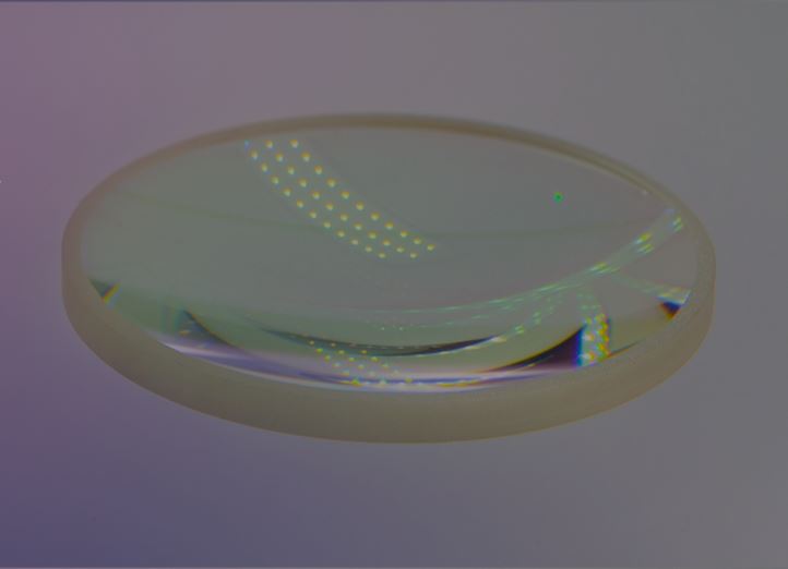
Filters and Mirrors for Laser Applications

Product information "Filters and Mirrors for Laser Applications"

The use of lasers as the illumination source for fluorescence applications requires special consideration for the optical path. This special attention centers on the coherent nature of the light, the small beam diameter, the polarization, and the power. There are also circumstances where cone angle and scatter within the system play significantly into the design of the optics.

Chroma Technology specializes in the design and manufacture of optical filters and coatings for applications that require extreme precision in color separation, optical quality, and signal purity. Chroma Technology’s portfolio comprises single bandpass and single edge filters, multi bandpass and multi band dichroic beamsplitters, complete filter sets for single band, longpass, shortpass and multi band as well as filter accessories.

Laser optics must be designed and made differently from standard widefield filters and mirrors. While it is true that most laser optics will work fine in widefield applications, the inverse is clearly not true, as shown by the different specifications in each case. The differences in design and construction may not be apparent to the end-user in every laser application. However, these differences will be painfully obvious in most experiments if these specifications are not met, especially with more demanding applications such as TIRF, Raman, and multi-photon microscopy.

While the entire beam path should be considered carefully, the downloadable “application note filters and mirrors for laser applications” emphasizes the filters and dichroic mirrors used in the beam path. Get in touch with the AMS Technologies optical filter experts today to find out which Chroma Technology optical and mirrors for laser applications can meet the demands and challenges of your project.

Key Features:

  • Extremely Durable
  • High-throughput Sputter-coated Filters
  • Very Broad Range of Filters for the Multitude of Fluorochromes Used in Epi-fluorescence Microscopy
  • Dichroic Beamsplitters With Various Spectral Profiles Available
  • Customized Filter Sets Available on Request
  • Transmission Level: up to 97%

Applications: Fluorescence Applications; TIRF (Total Internal Reflection Fluorescence); Raman Spectroscopy; Multi-photon Microscopy

Manufacturer "Chroma Technology"
Related links of the manufacturer

Similar products

Acousto-Optic Tunable Filters
Wavelength 351-4500 nm; Active Aperture 2-12 mm; Bandwidth 0.3-12 nm; Acousto-optic tunable filters (AOTF) are used to rapidly and dynamically select a specific wavelength from a broadband or multi-line laser source. As the applied RF frequency is varied, the transmitted wavelength changes, “tuning” the wavelength of the beam or image in tens of microseconds or less. An extensive line of AO tunable filters is available for wavelength from the UV through mid-IR, with resolution bandwidths of less than 1nm, with options such as large-aperture imaging filtering and sideband suppression. Fiber-coupled acousto-optic tunable filters devices are available upon request.AOTFs with apertures less than 6 mm are typically used that have less than tens of nm of resolution bandwidth at NIR wavelengths and less than ten nm at visible wavelengths. A quasi-collinear AOTF can deliver < 1 nm resolution bandwidth if operated with highly collimated light. AOTFs with larger apertures (> 6 mm) are a powerful tool for spectral imaging, rapidly and efficiently scanning an entire image in wavelength. This is of use in high-speed applications like hyperspectral imaging, confocal microscopy and on-line process control. The cost of AOTFs increases significantly for very large apertures, but they deliver unmatched speed for time-sensitive multispectral measurements in industry and biotech, approaching real-time video rate spectral imaging.  Gooch & Housego’s acousto-optic tunable filters are manufactured using high quality TeO2 crystals grown in-house, polished and fabricated to rigorous standards, with wavelengths from 350 nm to 4.4 µm in a wide variety of apertures and resolution bandwidths. It is possible to filter images up to 25 mm across, meet exceptionally low driver power requirements or design an AOTF to select and transmit multiple discrete wavelengths.Acousto-optic tunable filters often exhibit light leakage outside the resolution bandwidth of interest, typically at 10-20 dB below peak power. This is due to the response function of the AOTF itself but can be minimized using G&H’s patented techniques. Sideband suppression is available in several models, reducing out of band side lobes by greater than 20 dB relative to the primary beam. The AOTF product family includes application-specific solutions for illumination or excitation wavelength selection, as well as multispectral or hyperspectral imaging. For best performance, we recommend a matched RF driver, including the latest digital frequency synthesizer (DFS) driver technology and random access wavelength control. Applications: Confocal Microscopy; Fluorescence Imaging; Hyperspectral Imaging; Imaging Spectroscopy; Laser Wavelength Tuning; On-Line Process Control; Spectroscopy; Wavelength Selection Series Wavelength Active Aperture Bandwidth Downloads AOTF 2837-31 351 - 430 nm 2.5 mm 1.0 nm Datasheet      TF525-250-6-3-GH19A 400 - 650 nm 3 mm 3 nm Datasheet      AOTF 3151-01 400 - 650 nm 2.5 mm 2.5 nm Datasheet      TF550-300-4-6-GH57A AOTF 400 - 700 nm 6 mm 4 nm Datasheet      TF560-280-1-5-NT2 AOTF 420 - 700 nm 5 mm 0.3 nm Datasheet      AOTF 2838-01 450 - 670 nm 2.5 mm 1.3 nm Datasheet      AOTF 2885-02 450 - 670 nm 2.5 mm 2 nm Datasheet      AOTF 2885-04 450 - 670 nm 2.5 mm 4 nm Datasheet      TF625-350-2-11-BR1A AOTF 450 - 800 nm 11 x 12 mm 1.5 nm Datasheet      TF850-500-10-6-GH58A AOTF 600 - 1100 nm 6 mm 10 nm Datasheet      AOTF 2986-01 640 - 1100 nm 2.5 mm 5 nm Datasheet      TF950-500-1-2-GH96 700 - 1200 nm 2 mm 0.6 nm       AOTF 2996-01 1100 - 2000 nm 2.5 mm 12 nm Datasheet  Driver Driver I-TF1650-1100-1-3-GH107 1100 - 2200 nm 3 mm 1.0 nm       TF1875-1250-10-6-GH59A 1250 - 2500 nm 6 mm 10 nm Datasheet      I-TF2250-1500-2-3-GH107 1500 - 3000 nm 3 mm 2 nm       I-TF3250-2500-3-3-GH107 2000 - 4500 nm 3 mm 3 nm      
Product number: SW11458
Manufacturer:
Anti-Reflection Coating
Together with our supplier Vortex we provide broadband and V-style anti-reflection (AR) coating from 300 nm to 6000 nm. We offer AR coatings service on your optics with an unrivalled rapid turnaround or can also supply “make complete” AR-coated optics with substrates sourced through one of our trusted suppliers. Our AR coatings can be customized to your application’s requirements – contact the AMS Technologies experts today to discuss your customized anti-reflection coating solution! Broadband AR CoatingA number of standard broadband processes covering many spectral regions is available that can also be adjusted for your specific requirements, e.g. the coating’s properties can be moved to a number of different bands if required. Some examples of broadband AR coatings: Broadband AR Coatings    Optimized Wavelength Substrate Average Reflection Within Wavelength Band AR 400-700 nm Glass <0.5% AR 400-900 nm Glass <1.0% AR 400-1100 nm Fused Silica <1.0% AR 400-1700 nm Sapphire <3.5% AR 400-2500 nm Sapphire <8.0%   V-CoatingAs a special type of anti-reflective coating, V-coatings improve transmission in a very narrow wavelength range around the design wavelength. This type of coating is called a "V-coating" because the curve of the reflection over the wavelength resembles the letter "V", with a minimum at the design wavelength. Both single- and multiple-wavelength V-coat processes are available for laser and LED applications covering a range from 300 nm to 6000 nm, with maximum reflection of <0.25% per surface at the designated wavelength. Some examples of V-coatings: V-Coatings     Optimized Wavelength Substrate Reflection V-Coat 633 nm BK7 <0.25% V-Coat 1064 nm BK7 <0.25% V-Coat 1550 nm Sapphire <0.25% V-Coat 3300 nm CaF2 <0.25% V-Coat 532_1064 nm BK7 <0.25% V-Coat 532_1064_1550 nm BK7 <0.25% V-Coat 532_633_780_1064_1550 nm BK7 <0.25%   Infrared AR CoatingInfrared anti-reflection coating can be provided anywhere between 0.7 µm and 6 µm on Glass, Silicon, Germanium, Sapphire, Barium Fluoride, Calcium Fluoride, Gallium Arsenide etc. to suit your specification. Some examples of infrared AR coatings: Infrared AR Coatings     Optimized Wavelength Substrate Average Reflection Within Wavelength Band AR 400-1700 nm Sapphire <2% AR 400-2500 nm Sapphire <3% AR 1200-2500 nm Silicon <3% AR 1500-5000 nm Silicon <3% V-Coat 1550 nm Sapphire <0.25% @1550 nm per Surface AR 2000-5000 nm Germanium <3% AR 3000-5000 nm Silicon <3% AR 3000-5000 nm Germanium <3% V-Coat 3300 nm Silicon <0.25% @3300 nm per Surface
Product number: SW11884
Manufacturer:
Beamsplitters and Dichroic Filters
Together with our supplier Vortex, we are able to provide optical beamsplitters and dichroic filters that are placed in optical systems usually at 45° to separate (or combine) different wavebands or wavelengths. One band is reflected from the front surface, while the 2nd band is transmitted through. Vortex’s beamsplitters and dichroic filters can be used to separate different planes of polarization. Some examples of Vortex’s previous work: Beamsplitter for Visible Region to Split/Combine Two Wavelength Bands, 45° Beamsplitter to Separate Two Wavelength Bands in the Mid IR Region at 45° Mid IR Filter Used for Separating S and P Polarization Bands at 45° Polarizing Beam-Splitter for S and P Polarization for 1550 nm Laser at 45° Filter for Separation of Visible and Far Infrared at 45° We are happy to provide a unique beamsplitter or dichroic filter – designed, specified and manufactured to your application’s requirements. Contact the AMS Technologies experts today to discuss your customized beamsplitter or dichroic filter solution!
Product number: SW11883
Manufacturer:
Custom Optical Filters
OPTAplus designs and manufactures custom optical filters exactly tailored to the customer’s requirements. Custom optical filters are available with dimensions ranging from 3.0 mm to 200.0 mm. OPTAplus’ portfolio comprises custom optical filters made from a broad range of materials like various optical glasses, quartz glass, Borosilicate glass, color-filter glass as well as crystal materials like Si, Ge, MgF2, CaF2, Sapphire, etc. Polishing is available either one-side or double-side. On request, OPTAplus’ custom optical filters can be coated with a variety of coatings for the NIR, VIS and UV range for single wavelength or a spectral area, from single-layer or multi-layer anti-reflection (AR) coatings to metallic or dielectric reflective coatings to polarizing coatings. Please contact the AMS Technologies optical filter experts to discuss your customized optical filter solution that exactly matches your application’s requirements.
Product number: SW11596
Manufacturer:
Infrared Filters and Coatings
 0.7-6.0 µm; Transmittance >65%->85%; FWHM 42-190 nm; Diameter 25 mm; Thickness 0.5 mm; Surface Quality <60-40 Scratch-Dig  Vortex designs and makes a wide range of IR filters with center wavelengths from 0.7 µm to 6.0 µm. While traditionally thermal evaporation has been used for IR filters, Vortex IR filters are deposited by sputtering using the supplier’s “Rockard”© technology.  Sputter deposition has a process energy approximately three times that of thermal evaporation, leading to the filters’ densely packed structure. This technology ensures the following superior environmental and optical properties: Highly durable coatings suitable for the toughest environments Extremely low temperature shift Reduced passband ripple for even response High blocking efficiency to increase signal to noise ratio All IR filters are sold as 25mm diameter, 0.5mm thick and exhibit high angular tolerance, extremely low change with temperature and very high resistance to thermal shock.  AMS offers Vortex’s wide range of ‘standard’ narrow band IR filters for detection of common gases, chemicals and materials. For details and specifications see below: Standard Narrow Band Filters       Part Number CWL (nm) Transmittance FWHM (nm) Suggested Use NBP-1940-42-25 1940 nm (±8 nm) >85% 42 nm (±5 nm) H2O (Water) NBP-3055-145-25 3055 nm (±16 nm) >75% 145 nm (±17 nm) C2H2 (Acetylene) NBP-3260-150-25 3260 nm (±16 nm) >75% 150 nm (±17 nm) C2H4 (Ethylene) NBP-3330-150-25 3330 nm (±15 nm) >75% 150 nm (±15 nm) CH4 (Methane) NBP-3349-70-25 3349 nm (±15 nm) >75% 70 nm (±15 nm) C2H6 (Ethane) NBP-3400-155-25 3400 nm (±15 nm) >75% 155 nm (±15 nm) (HC) General Hydrocarbon NBP-3900-180-25 3900 nm (±18 nm) >75% 180 nm (±20 nm) (Reference) NBP-4000-180-25 4000 nm (±18 nm) >75% 180 nm (±15 nm) (Reference) NBP-4260-160-25 4260 nm (±20 nm) >70% 160 nm (±21 nm) CO2 (Carbon Dioxide) NBP-4530-85-25 4530 nm (±20 nm) >75% 85 nm (±10 nm) N2O (Nitrous Oxide) NBP-4660-165-25 4660 nm (±15 nm) >75% 165 nm (±15 nm) CO (Carbon Monoxide) NBP-5330-190-25 5330 nm (±25 nm) >65% 190 nm (±25 nm) NO (Nitrogen Monoxide)   General IR filters and coatings are available for applications such as non-contact temperature measurement, filter wheels and machine vision. For details and specifications see below: General IR Filters and Coatings       Part Number Transmission Peak Blocking Range Suitable Detectors Description BPF-VIST-IRBL-25 70% Ave. for 400-600 nm 0.65-5 µm+  Si Photodiode Type Visible Transmission from 400 nm to 600 nm and Blocking for Near-IR and Mid-IR BPF-1.3-2.5-25 90% Ave. for 1.3-2.5 µm UV and Visible to 1.2 µm, 2.6-3.8 µm PbS, MCT and Boltometer Type Transmits from 1.3 µm to 2.5 µm and Blocks Outside this Range SWP-1.4-2.6-25 90% Ave. for 1.4-2.6 µm 2.75-20 µm PbSe, MCT and Boltometer Type 90% Average Transmission for 1.4 µm to 2.6 µm, Blocks from 2.7 µm to 20 µm LWP-1.65-25 90% Ave. in Pass Band UV, Visible + Desired Part of IR PbS, MCT and Boltometer Type Long Wave Pass Filter, Transmits Above 1.65 µm and Blocks Below Back to UV BPF-2070-2510-25 90% Ave. For 1070-2510 nm, 60% @2050 nm and 2550 nm ±1% UV and Visible to 2.0 µm and 2.7-20 µm+ PbS, InGaAs and Boltometer Type Mid IR Wide Band Pass Filter for 2070 nm to 2500 nm, Used for Non-contact Temperature Measurement BPF-3.0-5.0-25-Si >90% Ave. 3-5 µm Band UV and Visible to 2.8 µm and 5.3-7.5 µm PbSe, MCT and Boltometer Type 90% Average Transmission from 3 µm to 5 µm, Blocks Outside this Range to 7.5 µm on Silicon BPF-3.0-5.0-25-SAP >90% Ave. 3-5 µm Band UV and Visible to 2.8 µm and 5.3-7.5 µm PbSe, MCT and Boltometer Type 90% Average Transmission from 3 µm to 5 µm, Blocks Outside this Range to 20 µm on Sapphire   Custom filters can be manufactured with short lead-times, contact the AMS Technologies filter experts today to discuss a customized filter solution tailored to your application’s requirements. Key Features: Center Wavelength Range: 0.7 µm to 6.0 µm Typical Bandwidth (FWHM): 42 nm to 190 nm Transmittance: >65% to >85% Diameter: 25 mm Thickness: 5 mm Surface Quality: <60-40 Scratch-Dig Highly Durable and Suitable for the Toughest Environments (RockArd© Deposition Technology) High Angular Tolerance Extremely Low Change With Temperature Very High Resistance to Thermal Shock Applications: Detection of Common Gases and Materials Like H2O, C2H2, C2H4, C2H6, HC, CO2, N2O, CO, NO; Non-contact Temperature Measurement; Filter Wheels, Machine Vision
Product number: SW11880
Manufacturer:
Infrared Linear Variable Filters (LVF)
0.9-5.0 µm; Transmission 50%-75%; FWHM 1%, 2% * Center λ; Dimensions 15x3.5 mm; Thickness 0.5 mm; Surface Quality <60-40 Scratch-Dig Infrared linear variable filters (LVF) are narrow band filters where the center or peak wavelength changes continuously along its length from one side to the other – and across the device’s full wavelength range. Vortex’s linear variable filters feature a narrow band profile with a “full width half maximum” (FWHM) bandwidth of 1% or 2% of peak wavelength. All of the Vortex infrared linear filters exhibit high angular tolerance, extremely low change with temperature and very high resistance to thermal shock. Our range of standard infrared linear variable filters allows customers to explore the technology but at a relatively low cost:  Standard Infrared Linear Variable Filters (LVF)       Part Number Wavelength Range Bandwidth (as a % of Center Wavelength) Basic Blocking Range Gradient of Change Dimensions (L x W x T) LVF 0.9-1.7-3.5-15-0.5-2% 0.9-1.7 µm 2% (Generation 1) UV-1.8 µm, OD>2.5 Ave. Outside the Transmission Band 60 nm/mm 15 x 3.5 x 0.5 mm LVF 1.3-2.6-3.5-15-0.5-2% 1.3-2.6 µm 2% (Generation 1) 1.2-2.6 µm, OD>2.5 Ave. Outside the Transmission Band 85 nm/mm 15 x 3.5 x 0.5 mm LVF 2.5-5.0-3.5-15-0.5-2% 2.5-5.0 µm 2% (Generation 1) 1.8-5.5 µm, OD>2.5 Ave. Outside the Transmission Band 165 nm/mm 15 x 3.5 x 0.5 mm LVF 0.9-1.7-3.5-15-0.5-1% 0.9-1.7 µm 1% (Generation 2) UV-1.8 µm, OD>3.5 Ave. Outside the Transmission Band 60 nm/mm 15 x 3.5 x 0.5 mm LVF 1.3-2.6-3.5-15-0.5-1% 1.3-2.6 µm 1% (Generation 2) 1.2-2.6 µm, OD>3.5 Ave. Outside the Transmission Band 85 nm/mm 15 x 3.5 x 0.5 mm  Vortex also designs and manufactures custom infrared LVFs, featuring different bandwidths, sizes (e.g. to suit the user’s detector window dimensions), etc. to meet your needs. Contact the AMS Technologies filter experts today to discuss a unique customized linear variable filter, designed, specified and manufactured to your application’s requirements. Key Features: Peak Wavelength Changes Continuously With Distance Across the LVF’s Length Transmission: 50% to 75% Across the Band To Extend the LVF’s Blocking Range, a Suitable Bandpass Filter Can Be Added Substrate Dimensions (LxW): 15 mmx 3.5 mm Substrate Thickness: 0.5 mm Surface Quality: <60-40 Scratch-Dig Key Features of Generation 2 Infrared Linear Variable Filters: 2 Ranges Covered, 0.9-1.7 µm and 1.3-2.5 µm Bandwidth (FWHM): 1% x Center Wavelength Blocking Greater Than OD 3.5 Average Outside Passband Specifically for Systems Where Higher Signal-to-noise Ratio is Critical Key Features of Generation 1 Infrared Linear Variable Filters: 3 Ranges Covered, 0.9-1.7 µm, 1.3-2.5 µm and 2.5-5.0 µm Bandwidth (FWHM): 2% x Center Wavelength Blocking Greater Than OD 2.5 Average Outside Passband Applications: Mini-spectrometers; Multi-gas Analysis; Industrial Process Monitoring; Other
Product number: SW11881
Manufacturer:
OC Optical Coatings
Spectral Range 300-2500 nm; Standard and Custom Optical Coatings; Fully Automated E-beam Ion Beam Assisted Deposition (IAD) Technology; High Power Handling; Hard Abrasion Resistant Dielectric Coatings Optical thin film coatings are used to change the spectral transmission and reflection behavior of optical surfaces to produce optical components with desirable spectral properties. Nowadays, almost all optical devices have some optical coating applied onto their optical surfaces. OZ Optics uses all-dielectric coating materials and designs that insure virtually no absorption, low loss and no scattering. OZ Optics specializes in coating high power optical components that are used in a variety of applications and industries, using state-of-the-art fully automated electron beam ion assisted technology for manufacturing. Below is a brief description of the coatings available from OZ Optics. we produce. custom designs and runs can also be produced per customer request – contact AMS Technologies for details. Antireflection (AR) Coatings – Laser Line, Wide Band, Dual Band Coatings:Antireflection (AR) coatings are required to increase light throughput, reduce back reflections and minimize stray light in an optical system over a desired spectral range. Optical elements including fiber tips, parallel plates, lenses, and prisms are all regularly antireflection coated. A large variety of antireflection coating designs are regularly used and available. These include AR coatings for: Major laser wavelengths, Dual-band (DBAR) antireflection coatings, Broadband (BBAR) antireflection coatings Custom designs for user-specified spectral regions. Plate Beamsplitters, Tap Coatings, Partial Reflectors:Beamsplitters are used to split reflected and transmitted light of a given spectral range at a specific ratio and predefined angle of incidence (usually 45 degrees). Examples include 50/50, 70/30, and 90/10 transmission/reflection ratios. This also includes control of the polarization states of the reflected and transmitted beams.Tap coatings are used to transmit light but to reflect (tap off) a small portion of light at usually small angles of incidence (e.g 1.8 degrees). 99/1 and 95/5 are common ratios. These are used in a variety of optical systems to measure and control the amount of light that is exiting the optical device (power monitoring). Longwave and Shortwave Pass Filters (Dichroics):Longwave and shortwave pass (also called edge filters, dichroic filters) transmit and reflect certain parts of the spectral range. These filters are designed and made for a predetermined angle of incidence (such as 0 or 45 degrees) or range of incident angles (eg. 0-20, 35-50 degrees), depending on the optical design of the device used. They are used for a variety of applications that require beam combining and separation based on wavelength.One example would be wavelength division multiplexers (WDMs). These devices are used to combine different incoming wavelengths into a single beam. For example, one could combine 532 nm and 633 nm wavelengths into one beam. Laser Line High Reflectors:High reflector mirrors reflect light over a predefined spectral range. Also, partial reflecting mirrors are made where a fixed portion of the light is transmitted. OZ Optics focuses on coating dielectric high reflectors on custom substrates or on fiber tips for a variety of applications. These coatings feature low absorbance, and high power handling. Typical reflectance is R> 99-99.9 %. Custom Optical Coatings:OZ Optics does custom coatings for a variety of applications. Please contact AMS Technologies with your request – we will send you a proposed design (spectral performance) and quote. Key Features: Standard and Custom Optical Coatings Available Fully Automated E-beam Ion Beam Assisted Deposition (IAD) Technology High Power Handling Low Temperature Deposition Hard Abrasion Resistant Dielectric Coatings Designed to Handle Large Volume of Fibers, Micro Optics, Lenses, Prisms, Windows and Uncommon Size Substrates Thin Film Design Capabilities for Custom Applications Spectral Range: 300 nm to 2500 nm Low and High Volume On-time Delivery and Competitive Pricing Applications: Fiber Optic Applications Like Sensors, Telecommunications; Lasers; Laser Spectroscopy; Laser to Fiber Delivery; Laser Pumping; Imaging Systems; Instrumentation Optics; General Photonics Applications; Custom Requests
Product number: SW11945
Manufacturer: