
IFA-100 Interferometric Fiber Analyser

Product information "IFA-100 Interferometric Fiber Analyser"

500 to 1000 nm; Refractive Index Accuracy ±0.0001; Spatial Resolution 500 nm; Fiber Type SM, MM, PM, Other; Fiber Diameter 40 to 400 µm

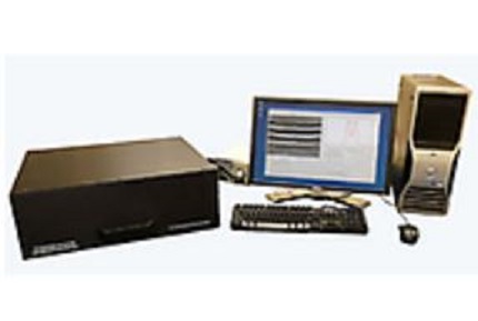
Interfiber Analysis’ IFA-100 multi-wavelength interferometric optical fiber analyzer can measure the refractive index profile of an optical fiber without the need for a cleave at wavelengths from 375 to 2000 nm.

By scanning the fiber from the side, the IFA-100 unit allows for scanning and measuring the optical refractive index profile (RIP) along the fiber’s length with sub-micron spatial resolution.

The measurement is independent of cumbersome fiber preparation like cleaving and allows for measuring the evolution of the refractive index profile over a given length of fiber. The equipment uses a broadband light source and can determine the refractive index profile at any wavelength between visible and near infrared.

The refractive index or index of refraction (IOR) is a property of any material. For optically transmitting materials, such as for fibers and waveguides, it is reflected in the reduced speed of light when travelling through any media other than vacuum.

Fibers and waveguides use a distribution of the IOR within their cross section to guide and reflect light, and knowledge of this distribution allows many other critical performance parameters to be calculated, such as mode fields, group and phase propagation constants and fiber dispersion.

Based on Interfiber Analysis’ IFA-100 multi-wavelength interferometric optical fiber analyzer, AMS Technologies offers refractive index measurement services for product development, incoming inspection and forensic analysis on optical fibers.

Key Features:

  • Multi-wavelength: 500 to 1000 nm
  • No Cleave Required
  • Sub-µm Spatial Resolution: About 500 nm
  • Applicable to Any Fiber Type
  • Fast Measurement
  • Refractive Index Accuracy: ±0.0001
  • Fiber Diameter: 40 to 400 µm
  • Fiber Material: Silica Glass, Non-silica Glass, Plastic
  • Concentricity Error Measurement: ±200 nm
  • Core Non-circularity Error Measurement: ± 0.4%
  • Fiber Type: Single Mode (SM), Multi Mode (MM), Polarization Maintaining PM), Micro-Structured (PCF), Multicore, Rare-earth, Cladding-pumped, Large Mode Area (LMA), Low Bend Loss, High-Δ, etc.


Applications: Measuring Splices, Tapers or Couplers of Any Fiber Type; Test and Measurement; Telecommunication; Lasers

Manufacturer "Interfiber Analysis "
Interfiber Analysis provides optical fiber measurement instruments and an array of consulting services. The US-based company manufactures the world's first commercially available refractive index profiler for optical fibers that allows for scanning the optical index of refraction (RIP) along its length. The consulting services include engineering analysis and numerical modelling, fusion splice analysis and forensic analysis of optical fiber failure.
Related links of the manufacturer

Customers also viewed

YEDFA-PM-SO EDFA Racks
Polarization Maintaining, Yb/Er Co-doped; 1543 to 1565 nm; Input Power -10 to +10 dBm; Output Power 27 to 33 dBm; 110 to 240 VAC LightComm Technology’s YEDFA-PM-SO series of high-power polarization maintaining fiber amplifiers are designed to output optimal optical performance with high reliability and stability. These amplifiers are especially developed for PM transmission, sensors and LIDAR applications. The YEDFA-PM-SO line of PM high power fiber amplifiers features a dual stage amplification configuration, pre-amplifier and power amplifier, the use of selected components with extremely high polarization extinction ratio and low insertion loss values, and the careful management of splice joints to preserve polarization.Both input and output signals are sampled and monitored with a feedback circuit to protect the amplification system. APC (automatic power control), AGC (automatic gain control) and ACC (automatic current control) circuits are designed into the amplifier to ensure high stability and reliability of output power. Standard user-friendly Ethernet or RS-232 network interface enables reliable connectivity with the customer’s network management system. Key Features: High Polarization Extinction Ratio Low Noise Figure RS-232 or Ethernet Interface Highly Reliable Laser Diode Pumps High Stability and Reliability Based on Multi-mode Pump and PM Fiber Combining Technology Applications: LIDAR & Sensor; Test and Measurement; Coherent Synthesizing & Spectrum Synthesizing; Frequency Conversion; Microwave Optics; Booster Amplifier for PM Transmitters
Product number: SW10485
Manufacturer:

Infrared Filters and Coatings
 0.7-6.0 µm; Transmittance >65%->85%; FWHM 42-190 nm; Diameter 25 mm; Thickness 0.5 mm; Surface Quality <60-40 Scratch-Dig  Vortex designs and makes a wide range of IR filters with center wavelengths from 0.7 µm to 6.0 µm. While traditionally thermal evaporation has been used for IR filters, Vortex IR filters are deposited by sputtering using the supplier’s “Rockard”© technology.  Sputter deposition has a process energy approximately three times that of thermal evaporation, leading to the filters’ densely packed structure. This technology ensures the following superior environmental and optical properties: Highly durable coatings suitable for the toughest environments Extremely low temperature shift Reduced passband ripple for even response High blocking efficiency to increase signal to noise ratio All IR filters are sold as 25mm diameter, 0.5mm thick and exhibit high angular tolerance, extremely low change with temperature and very high resistance to thermal shock.  AMS offers Vortex’s wide range of ‘standard’ narrow band IR filters for detection of common gases, chemicals and materials. For details and specifications see below: Standard Narrow Band Filters       Part Number CWL (nm) Transmittance FWHM (nm) Suggested Use NBP-1940-42-25 1940 nm (±8 nm) >85% 42 nm (±5 nm) H2O (Water) NBP-3055-145-25 3055 nm (±16 nm) >75% 145 nm (±17 nm) C2H2 (Acetylene) NBP-3260-150-25 3260 nm (±16 nm) >75% 150 nm (±17 nm) C2H4 (Ethylene) NBP-3330-150-25 3330 nm (±15 nm) >75% 150 nm (±15 nm) CH4 (Methane) NBP-3349-70-25 3349 nm (±15 nm) >75% 70 nm (±15 nm) C2H6 (Ethane) NBP-3400-155-25 3400 nm (±15 nm) >75% 155 nm (±15 nm) (HC) General Hydrocarbon NBP-3900-180-25 3900 nm (±18 nm) >75% 180 nm (±20 nm) (Reference) NBP-4000-180-25 4000 nm (±18 nm) >75% 180 nm (±15 nm) (Reference) NBP-4260-160-25 4260 nm (±20 nm) >70% 160 nm (±21 nm) CO2 (Carbon Dioxide) NBP-4530-85-25 4530 nm (±20 nm) >75% 85 nm (±10 nm) N2O (Nitrous Oxide) NBP-4660-165-25 4660 nm (±15 nm) >75% 165 nm (±15 nm) CO (Carbon Monoxide) NBP-5330-190-25 5330 nm (±25 nm) >65% 190 nm (±25 nm) NO (Nitrogen Monoxide)   General IR filters and coatings are available for applications such as non-contact temperature measurement, filter wheels and machine vision. For details and specifications see below: General IR Filters and Coatings       Part Number Transmission Peak Blocking Range Suitable Detectors Description BPF-VIST-IRBL-25 70% Ave. for 400-600 nm 0.65-5 µm+  Si Photodiode Type Visible Transmission from 400 nm to 600 nm and Blocking for Near-IR and Mid-IR BPF-1.3-2.5-25 90% Ave. for 1.3-2.5 µm UV and Visible to 1.2 µm, 2.6-3.8 µm PbS, MCT and Boltometer Type Transmits from 1.3 µm to 2.5 µm and Blocks Outside this Range SWP-1.4-2.6-25 90% Ave. for 1.4-2.6 µm 2.75-20 µm PbSe, MCT and Boltometer Type 90% Average Transmission for 1.4 µm to 2.6 µm, Blocks from 2.7 µm to 20 µm LWP-1.65-25 90% Ave. in Pass Band UV, Visible + Desired Part of IR PbS, MCT and Boltometer Type Long Wave Pass Filter, Transmits Above 1.65 µm and Blocks Below Back to UV BPF-2070-2510-25 90% Ave. For 1070-2510 nm, 60% @2050 nm and 2550 nm ±1% UV and Visible to 2.0 µm and 2.7-20 µm+ PbS, InGaAs and Boltometer Type Mid IR Wide Band Pass Filter for 2070 nm to 2500 nm, Used for Non-contact Temperature Measurement BPF-3.0-5.0-25-Si >90% Ave. 3-5 µm Band UV and Visible to 2.8 µm and 5.3-7.5 µm PbSe, MCT and Boltometer Type 90% Average Transmission from 3 µm to 5 µm, Blocks Outside this Range to 7.5 µm on Silicon BPF-3.0-5.0-25-SAP >90% Ave. 3-5 µm Band UV and Visible to 2.8 µm and 5.3-7.5 µm PbSe, MCT and Boltometer Type 90% Average Transmission from 3 µm to 5 µm, Blocks Outside this Range to 20 µm on Sapphire   Custom filters can be manufactured with short lead-times, contact the AMS Technologies filter experts today to discuss a customized filter solution tailored to your application’s requirements. Key Features: Center Wavelength Range: 0.7 µm to 6.0 µm Typical Bandwidth (FWHM): 42 nm to 190 nm Transmittance: >65% to >85% Diameter: 25 mm Thickness: 5 mm Surface Quality: <60-40 Scratch-Dig Highly Durable and Suitable for the Toughest Environments (RockArd© Deposition Technology) High Angular Tolerance Extremely Low Change With Temperature Very High Resistance to Thermal Shock Applications: Detection of Common Gases and Materials Like H2O, C2H2, C2H4, C2H6, HC, CO2, N2O, CO, NO; Non-contact Temperature Measurement; Filter Wheels, Machine Vision
Product number: SW11880
Manufacturer:

2D Mode Solver Software
Wavelength Band UV-SWIR, 400-2150 nm; Scalar FEM Numerical Engine; Solution in Seconds; ASCII Fiber Profile Input & Data Output; System Requirements 64-bit MS Windows Based on fiber refractive index profile data, Interfiber Analysis’ “2D Mode Solver” software package computes guided modes and mode properties, fiber bending/coiling effects, as well as mode coupling at splices. The software tool can analyze either 1-dimensional or 2-dimensional fiber index data so it can quantify the impact of any asymmetries in the fiber index profile. With this tool, you can: Compute 2-dimensional fiber modefields and mode properties Predict mode coupling at fiber splices Model fiber bending effects Quantify impact of index profile asymmetries Determine overlap between modes and cores Analyze fiber, preform, or synthetic index profiles These capabilities make the software particularly useful for customers working with high-power optical fibers. It is not only useful for existing IFA-100 users (who can use it to compute modes based on their IFA-100 data,) but also for those who use other equipment as it can be applied to fiber index data from other measurement devices (including preform profilers). This very attractively priced software tool runs on MS Windows 64-bit computers, and unlike other competing software packages, we offer multiple licenses at the customer location for the price of a single purchase. Key Features: System Requirements: MS Windows 64-bit Computer Numerical Engine: Scalar Finite Element Method (FEM) Wavelength Band: UV to SWIR (400 nm to 2150 nm) Solution Domain: 140 µm Diameter Disk Solution Time: Seconds Fiber Profile Input: ASCII Text Files (1- and 2-dimensional) Data Output: ASCII Text, PNG or PDF Images Computed Mode Properties: Electric Field, Optical Intensity, Effective Index, Group Index, Dispersion, Mode Field Diameter, Effective Area Applications: Computing of Guided Modes, Mode Properties, Fiber Bending/Coiling Effects, Mode Coupling at Splices
Product number: SW11786
Manufacturer:

Refractive Index Measurement Services
Measurement of 1-D, 2-D, 3-D Fiber Refractive Index Profiles; No Costly Instrument Purchase; 500 to 1000 nm; Refractive Index Accuracy ±0.0001; Spatial Resolution 500 nm Based on Interfiber Analysis’ IFA-100 multi-wavelength interferometric optical fiber analyzer, AMS Technologies offers refractive index measurement services for product development, incoming inspection and forensic analysis on optical fibers. At our testing facility in Munich we can secure quick sample turnaround and offer confidentiality of measurement results. The refractive index profile allows determination of key transmission parameters like chromatic dispersion, mode field diameter, bandwidth, birefringence and polarization mode dispersion (PMD). Line plots and tomography scans: The measurements can be taken in one dimension giving a line plot of the refractive index at any given cross section of the fiber. This measurement assumes the fiber to be symmetrical, and symmetrical geometry is assumed for the computation of the refractive index profile. For the two-dimensional measurements, several lower-dimensional projections are combined to form a full surface profile of the refractive index. This computer tomography based approach does not take assumptions for the fibers being symmetric. Environmental testing solution: The interferometry measurement technique used in the setup does not require external calibration. Measurements can be done with fiber diameters from 40 to 400 µm within a measurement wavelength from 500 to 1000 nm. Fiber material can be silica glass, non-silica glass or plastic. The accuracy of index of refraction is ±0.0001, accuracy of stress measurement is ±5 MPa. Contact AMS Technologies’ fiber property measurement experts to find out how our refractive index measurement services can solve your measurement challenges! Key Features: Measurement of 1-D, 2-D, and Even 3-D Fiber Refractive Index Profiles No Costly Instrument Purchase Rapid Turnaround Experienced Measurement Staff Any Fiber Type: Single Mode (SM), Multi Mode (MM), Polarization Maintaining PM), Micro-Structured (PCF), Multicore, Rare-earth, Cladding-pumped, Large Mode Area (LMA), Low Bend Loss, High-Δ, etc. Any Fiber Material: Silica, Non-silica, Plastic Any Fiber Diameter From 40 to 750 μm Any Measurement Wavelength From 500 to 1000 nm Sub-μm Fiber Geometry Measurements Sample Lengths Can be as Sort as Centimeters Refractive Index Accuracy: ±0.0001 Sub-µm Spatial Resolution: About 500 nm No Cleave Required Fiber Diameter: 40 to 400 µm Fiber Material: Silica Glass, Non-silica Glass, Plastic Concentricity Error Measurement: ±200 nm Core Non-circularity Error Measurement: ± 0.4% Applications: One-Dimensional Refractive Index Measurement; Two-Dimensional Refractive Index Measurement; One-Dimensional Stress Measurement; Three-Dimensional Refractive Index Measurement
Product number: SW11079
Manufacturer:

PER-KIT Polarization Extinction Ratio Measurement Test Set
1290-1650 nm; No. of Channels 1; PER Resolution 0.01 dB; PER Dynamic Range 47 dB; Angular Resolution 0.3°; Input Optical Power Range 50-1000 µW; Source Output Power 1 mW OZ Optics has bundled its polarized sources, polarization extinction ratio meters and master reference patchcords into the PER-KIT – one complete test set for rapid testing of the polarization maintaining properties of optical components. We offer systems for testing devices terminated with connectors, as well as systems for testing the polarization properties of V-Groove arrays. For standard components, the extinction ratio measurement system includes a polarized source with a rotatable polarizer, a polarization extinction ratio meter, a quick connect adaptor for the extinction ratio meter, and a reference polarization maintaining patchcord. For V-Groove arrays, OZ Optics offers an OEM version of the polarization measurement system (manual operated type and semi-automated type). The test set includes the polarized source with rotatable polarizer, an OEM version of the extinction ratio meter with external optics, a V-Groove mount with a three-axis position system, with one axis motorized for semi-automated type, a reference V-Groove array with a single PM fiber, and an application software package for semi-automated type. The user only has to supply a Windows-based computer to operate the system as a semi-automated test bed. Key Features: Measures Extinction Ratios up to 40 dB Complete Kit for Extinction Ratio (ER) Measurement Simple Operation Key Features PFOSS-02 Polarized Sources: Laser Type: Fabry-Perot Laser Central Wavelength: 1550 nm ±20 nm, 1310 nm ±20 nm Extinction Ratio: 40 dB, 35 dB Output Power: 1 mW Polarizer Type: Rotatable Spectral Bandwidth: <5 nm Short Term Stability: ±0.05 dB Long Term Stability: ±0.1 dB Connector Type: Standard, Super, Ultra NTT-FC/PC Receptacle Power Variation Induced by Rotatable Polarizer: <0.25 dB Supply Voltage: Universal 110/220 VAC to DC Adapter Dimensions: 76 x 63 x 70 mm Key Features ER-100 Extinction Ratio Meter: Wavelength Range: 1290 nm to 1650 nm Extinction Ratio Range: 40 dB (for 1290 nm to 1650 nm) Dynamic Range: 47 dB Polarization Extinction Ratio Accuracy: ±1 dB Polarization Extinction Ratio Resolution: 0.01 dB Angular Accuracy: ±0.5° Angular Resolution: 0.3° Update Rate (Extinction Ratio): 2.7 Hz Update Rate (Relative Power): 650 Hz Input Optical Power: 50 μW to 1.0 mW Communication Interface: RS232 Supply Voltage: Universal 110/220V VAC to DC Adapter, 50/60 Hz Dimensions: 60 x 90 x 190 mm Weight: 0.5 kg (5 kg for V-Groove Array Measurement Test Set) Operating Temperature: +10°C to +50°C Regulatory Compliance: Complies With EMC (EN61326:1997 & A1:1998) and Safety Requirements (EN61010-1:1993, A2:1995) Applications: Fiber Optic Component Manufacturing; Automated Alignment; Quality Control and Measurement; Product Development; Component or System Troubleshooting
Product number: SW11948
Manufacturer: