
VGC V-Groove Chips

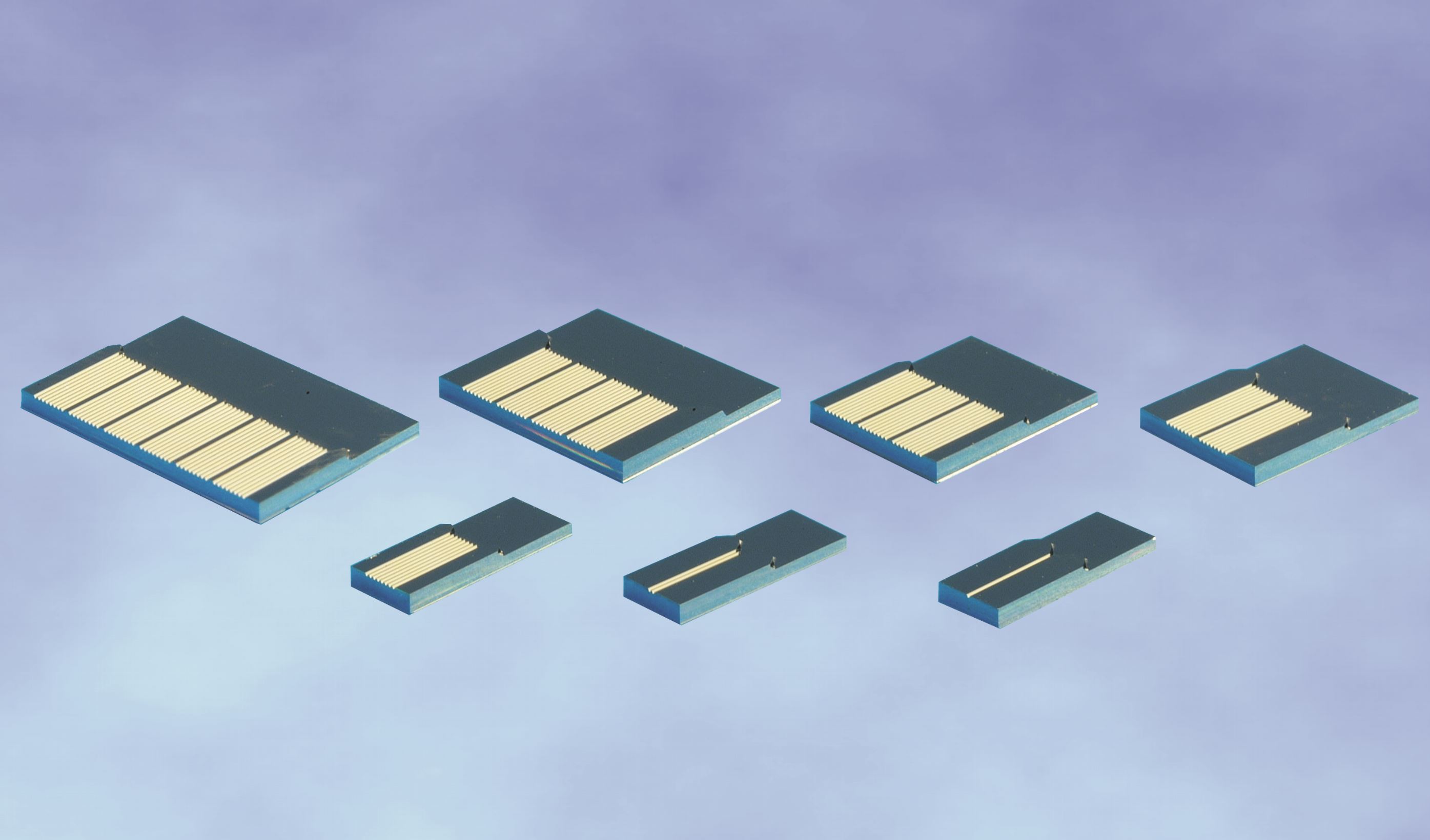
Product information "VGC V-Groove Chips"

1 to 48 Channels; Channel Spacing 250 µm; Dimensions 10.4 x 3.8 x 1 to 10.4 x 14.8 x 1 mm; Matching Pyrex Lids; Fiber Type SM, MM, PM

OZ Optics’ VGC series of V-Groove chips assists in developing next generation photonic devices. The array components allow precise alignment of up to 48 either ribbonized or individual fibers in a linear array. Utilizing VGC V-Grooves with a Pyrex lid allows UV or heat curing of the fibers into the array and attachment to another device.

The side wall design incorporated in the rear of the V-Groove chip enhances the overall assembly’s strength and rigidity and reduces breakages. Standard channel spacing is 250 µm, other channel spacings are available upon request - for further information, please contact the AMS Technologies optical fiber experts.

Key Features:

  • Up to 48 Channel V-Groove Arrays
  • High-Accuracy V-Grooves Using Etched Silicon or Machined Glass
  • Compatible With 125/250 µm Diameter Single Mode (SM), Multi Mode (MM) and Polarization Maintaining (PM) Fibers
  • 0.5 µm Channel Spacing Accuracy
  • Designed to Meet Telcordia Requirements
  • Silicon and Glass Versions


Applications: Pigtailing of Integrated Optical Devices; Connection to Planar Waveguide Devices; Attachment to an Array of Active Devices; Connection of MEMS Devices and Miniaturized Fiber Optic Components; Construction of DWDM and Multi-channel Devices

Manufacturer "OZ Optics"
Related links of the manufacturer

Similar products

START/ALIGN Alignment Kits and Tools
For Pigtail-style or Receptacle-Style Couplers (FC, FC/APC, FC/AFC, ST, SC, or Angled SC); Wavelength Ranges 180-700, 400-1600 nm; Includes MM Patchcord or Fiber Assembly, Collimating Wrench (ALIGN), Polarization Alignment Jig (POL-ALIGN) and Video/DVD Key to successful alignment of any laser to fiber coupler is the initial task of getting the focused light to strike the core of the single mode (SM) or polarization maintaining (PM) fiber. OZ Optics' START alignment kits for laser to fiber couplers and ALIGN alignment kits for laser diode to fiber couplers simplify this task significantly by first using a multi mode (MM) fiber with a larger, relatively easy to target 50 µm core as the output fiber. Then by observing the output pattern from the MM fiber, one can improve the alignment, so the light is striking very close to the center of the fiber. Once this alignment is optimized, the MM fiber is removed and replaced with the SM or PM fiber. If done correctly, it should only take minor adjustments to successfully couple light into the SM or PM fiber. A video or DVD clearly shows how to align laser and laser diode to fiber couplers using these kits in a clear, step-by-step fashion. START and ALIGN alignment kits are available for both receptacle- and pigtail-style laser to fiber couplers. Perhaps the most difficult task is to align the polarization axis of lasers to the polarization axis of PM fibers. The POL-ALIGN polarization alignment tool makes this adjustment in seconds. The tool consists of a connector that fits the receptacle on the laser to fiber coupler. Inside the connector is a polarizer, aligned 90 degrees to the key on the connector. A laser to fiber coupler’s tilt screws and locking screws must be tightened with just the correct torque. To address this concern, a dedicated torque screwdriver is available. Key Features: Simplifies Alignment of Laser to Fiber Couplers Video/DVD Instructions Explains the Process Step by Step Reduces Your Assembly Time Completely Reusable Inexpensive Polarization Tool Gets Alignment Right the First Time Optional Torque Screwdriver Ensures Parts Are Tightened Correctly Wavelength Range: IRVIS (400 nm to 1600 nm), UVVIS (180nm to 700 nm) Suitable for:   Pigtail-style Couplers With 4, 8, 12 mm OD lens housings Receptacle-style Couplers with NTT-FC, Super NTT-FC, Ultra NTT-FC, NTT-FC/APC, Adjustable Focus NTT-FC/APC, NTT-FC/AFC, AT&T-ST, SC, or Angled SC Fiber Connector  Applications: Alignment of Laser to Fiber Couplers and Laser Diode to Fiber Couplers With SM or PM Fibers
Product number: SW11901
Manufacturer:
UB U-Bracket Assemblies
Tilt Adjustment Technique; Pigtail or Receptacle Style; Fiber Type SM, MM, PM; Typ. Insertion Loss 1 dB; Size 29 x 25 x 43 to 77 x 64 x 72 mm OZ Optics’ UB series of fiber optic U-bracket assemblies are designed to transmit light from an optical fiber, across an air gap, and back into a second fiber with low losses. The U-bracket is pre-aligned at the factory for minimum insertion losses, making it very easy to use. A variety of bulk optical devices, including polarizers, isolators, filters, and waveplates, can be simply inserted into the U-bracket, allowing the user to quickly and easily test or prototype systems incorporating fiber and bulk optics. The U-bracket assembly consists of three parts: an input fiber collimator, the U-bracket itself and an output fiber focuser. Utilizing OZ Optics' patented tilt adjustment technique, losses of only 0.6 dB are achieved across a 60 mm gap for pigtailed single mode fibers, with back reflection levels of -25, -40 or -60 dB available. Connector style assemblies are also available for a variety of connectors, including NTT-FC, AT&T-ST, bare fiber adapters, etc. Typical insertion losses are 1.0 dB across a 60 mm gap for connectorized versions, with back reflection levels of typically -20 dB. U-Brackets are available in different sizes, with different gap spacings according to the customer's needs. Many different custom designs can be made for your application. For instance, source to fiber versions are available, where light from either a laser, a laser diode or a LED is transmitted across the air gap and into the output fiber. Another option is to have a photo detector attached to the output end of the U-bracket to measure the transmitted light. Another device available is a black box with a removable filter holder, to quickly insert and remove a filter from the optical path. Contact the AMS Technologies fiber optic expert team to discuss your project’s requirements and find your custom U-bracket solution. Key Features: Pre-aligned Fiber Launch and Re-collect Small and Large Body Available Optional Removable Filter Holder Available Available in Single Mode (SM), Polarization Maintaining (PM) and Multi Mode (MM) Versions Low Insertion Loss High PER for PM Applications Compact Housing or Wide Free-space Air-gap Wide Beam Sizes Available Applications: Sample Interrogation; Prototyping Pigtailed Optical Devices; Polarization Control; Filters; Spectroscopy
Product number: SW10867
Manufacturer:

Customers also viewed

OPM Directional Fiber Optic Power Monitors
320 to 2100 nm; Tap Ratio 0.5 to 4%; Insertion Loss <0.05 to 0.3 dB; Return Loss >70 dB; Fiber Type SM, MM, PM, PC, Other; Power Handling 250 to 2000 mW With the OPM series, OZ Optics offers inline optical power monitors and tap couplers based on a revolutionary, patented technology. These taps and monitors provide a way to easily measure the signal intensity through an optical fiber in a simple, miniature package and are ideal for real time monitoring and feedback for optical amplifiers or WDM systems as well as for fiber optic sensors. Traditional monitoring systems typically use fused couplers to tap a fixed amount of light into another fiber that guides the optical power to a photodiode. This method is bulky and must be done using discrete components. In contrast, OZ Optics' OPM series of optical taps direct a controlled amount of light from the fiber core to the cladding surface where it can be directly monitored with high efficiency and very low loss. This inline tapping is accomplished without bending, shaping, or otherwise distorting the fiber. As a result, the tap can be directly incorporated into optical assemblies, without affecting the original functionality. While taps are directional in nature (ideal for monitoring traffic independently of signals travelling back through a network link), bi-directional versions are also available and can be provided on request. OPM taps can be fabricated into standard single mode (SM), polarization maintaining (PM), multi mode (MM), photonic crystal (PC) and other specialty fibers, for any design wavelength and with different tap ratios available upon request. OPM optical power monitors combine the optical tap design with a photodiode in an integrated package and are available in different configurations with Si and InGaAs detectors for different wavelength ranges. The devices produce a current proportional to the optical power within the fiber, and the small size and simple interface makes it very easy to design into optical hardware. Multiple channel power monitors for WDM applications are available upon request. Key Features: Miniaturized Package Inline Integration Without Interruption to the Optical Path Telcordia GR-468 Qualified Available for Any Wavelength from 400 to 2100 nm Low Insertion Loss, Return Loss and Polarization Dependent Loss High Directivity and Large Dynamic Range Broadband Response High Power Handling High Extinction Ratios for PM Versions Remotely and Locally Controllable, USB and RS232 Communication Options Available for Standard Telecom Fibers, PM, MM, Photonics Crystal and Other Speciality Fibers Available with or without Integrated Photodiode Applications: Power Monitoring; Optical Power Control Devices; Channel Balancing for Wavelength Division Multiplexing (WDM) Systems; Dynamic Optical Amplifier Gain Monitoring; FTTH Network Monitoring; Real-time Inline Test and Measurement; Fiber Optic Sensors; OCT Systems
Product number: SW10911
Manufacturer:
UB U-Bracket Assemblies
Tilt Adjustment Technique; Pigtail or Receptacle Style; Fiber Type SM, MM, PM; Typ. Insertion Loss 1 dB; Size 29 x 25 x 43 to 77 x 64 x 72 mm OZ Optics’ UB series of fiber optic U-bracket assemblies are designed to transmit light from an optical fiber, across an air gap, and back into a second fiber with low losses. The U-bracket is pre-aligned at the factory for minimum insertion losses, making it very easy to use. A variety of bulk optical devices, including polarizers, isolators, filters, and waveplates, can be simply inserted into the U-bracket, allowing the user to quickly and easily test or prototype systems incorporating fiber and bulk optics. The U-bracket assembly consists of three parts: an input fiber collimator, the U-bracket itself and an output fiber focuser. Utilizing OZ Optics' patented tilt adjustment technique, losses of only 0.6 dB are achieved across a 60 mm gap for pigtailed single mode fibers, with back reflection levels of -25, -40 or -60 dB available. Connector style assemblies are also available for a variety of connectors, including NTT-FC, AT&T-ST, bare fiber adapters, etc. Typical insertion losses are 1.0 dB across a 60 mm gap for connectorized versions, with back reflection levels of typically -20 dB. U-Brackets are available in different sizes, with different gap spacings according to the customer's needs. Many different custom designs can be made for your application. For instance, source to fiber versions are available, where light from either a laser, a laser diode or a LED is transmitted across the air gap and into the output fiber. Another option is to have a photo detector attached to the output end of the U-bracket to measure the transmitted light. Another device available is a black box with a removable filter holder, to quickly insert and remove a filter from the optical path. Contact the AMS Technologies fiber optic expert team to discuss your project’s requirements and find your custom U-bracket solution. Key Features: Pre-aligned Fiber Launch and Re-collect Small and Large Body Available Optional Removable Filter Holder Available Available in Single Mode (SM), Polarization Maintaining (PM) and Multi Mode (MM) Versions Low Insertion Loss High PER for PM Applications Compact Housing or Wide Free-space Air-gap Wide Beam Sizes Available Applications: Sample Interrogation; Prototyping Pigtailed Optical Devices; Polarization Control; Filters; Spectroscopy
Product number: SW10867
Manufacturer:
CLETOP Replacement Tape Blue CLE-14100700 (1 set = 6 tapes)
CLETOP Replacement Tape Blue (6 pcs/set) CLE-14100700 Blue Cletop Replacement Tape, Qty, 6 Tapes per Box, Sold by the Box, Replaces tape on Cletop Cassette Cleaners for Type A: 14100501, Type B: 14100601, Type MT-RJ: 141001, Type MPO: 14100201
Product number: C007907-6
Manufacturer:

Content: 6 pcs (€21.25* / 1 pcs)

€127.48*