VDL-001 Fiber Optic Delay Line

Product information "VDL-001 Fiber Optic Delay Line"

840-1650 nm; Delay Range 0-1,200 ps; RL 50 dB; Fiber Type SMF-28, HI780, HI1060, PM Panda; IL 1.0, 1.5 dB; PDL 0.1 dB

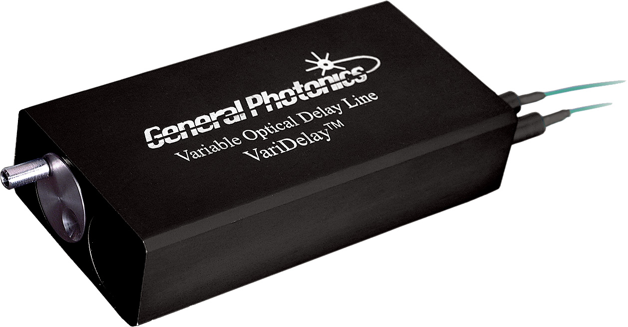
The General Photonics VDL-001 module is a manually controlled variable fiber optic optical delay line. Multiple versions are available with path length of up to 1,200 ps. A low insertion loss and low variation of insertion loss is critical for most applications, and the VDL-001 has less than ±1 dB variation even up to 1,200 ps.

The delay line is packaged in a small aluminum box to prevent dust or noxious vapors from contaminating the optical path. The compact, rugged design makes the VDL-001 device ideal for integration in network equipment, test instruments, and optical coherence tomography (OCT) systems for precision optical path length or timing alignment.

Key Features:

  • Highest Delay-to-Length Ratio
  • Optical Delay: Up to 1,200 ps
  • Insertion Loss (IL): 1.0, 1.5 dB Typical
  • Low Insertion Loss Variation: ±0.3, ±0.5, ±0.7 dB
  • Operating Wavelengths: 840, 1060, 1310, 1550, 1260 to 1650 nm
  • Optical Delay Range: 0 to 330, 0 to 600, 0 to 1200 ps
  • Readout Scale Resolution: 0.05 mm
  • Polarization Dependent Loss (PDL): 0.1 dB (SM Model)
  • Return Loss (RL): 50 dB
  • Extinction Ratio: >18 dB (PM Model)
  • Optical Power Damage Threshold: 300 mW
  • Fiber Type: SMF-28, HI780, HI1060, PM Panda
  • Dimensions: 25.5 x 53 x 107/152 mm

Applications: Optical Coherence Tomography (OCT) Systems; Passive Time Division Multiplexing (TDM); TDM Bit Alignment; Fiber Interferometers

Manufacturer "General Photonics"
Related links of the manufacturer

Similar products

DDL-650-11 Differential Polarization Delay Lines
Varies Delay Between Polarization States; Delay Range ±50 ps; Delay Resolution 0.0027 ps; Return Loss -40, -50, -60 dB; Max. Insertion Loss 1.2 dB OZ Optics’ DDL-650-11 differential polarization delay lines represent the next stage in controlling polarization mode dispersion in optical networks. The devices split the light within a fiber into orthogonal polarizations, and then actively vary the time that one polarization travels compared to the other polarization before combining the two polarizations together again. With this technique, one can introduce up to ±50 ps of optical delay in a system. The resolution of the DDL-650-11 differential polarization delay lines is better than 0.003 ps, thus providing a high degree of control. The devices are easily controlled by a computer via an RS-232 interface. Home and end position sensors allow easy monitoring of the device status and prevent any potential damage to the device. Key Features: Varies the Delay Between Two Polarization States Low Loss Sub-picosecond Delay Resolution: Wide Wavelength Range Delay Range: ±50 ps Delay Resolution: 0.0027 ps Max. Insertion Loss (IL): 1.2 dB Polarization Dependent Loss (PDL): <0.25 dB Return Loss: -40 dB, -50 dB, -60 dB Zero Delay Accuracy: ±0.1 ps Repeatability: <0.05 ps Speed: 3 ps/s Electronically Controlled Interface: RS232 or TTL Supply Voltage: 6 V to 8 V, max. 180 mA Dimensions: 105 x 51 x 25 mm Applications: PMD Compensation in High-speed Communications Networks; PMD Emulation; TDM Bit Alignment; Interferometric Sensors; Coherent Telecommunications
Product number: SW11909
Manufacturer:

FDE-002 Fixed Differential Group Delay
1550 nm; DGD 0-45 ps; RL 55 dB; IL 0.8 dB; Fiber Type SMF-28; PDL <0.2 dB General Photonics’ FDE-002 fixed differential group delay (DGD) artifacts eliminate the need for precise measurement of polarization maintaining (PM) fiber lengths to add defined amounts of first order PMD to a system. DGD values of up to 45 ps are available in the FDE-002 fixed differential group delay standard size package. Larger DGD values are also available by special request. Key Features: Large 1st Order PMD: up to 45 ps Low Insertion Loss (IL): <1 dB (0.8 dB Typical) Operating Wavelength: 1550 ± 50nm DGD Value: 0 to 45 ps Standard, Larger Values on Request DGD Calibration Accuracy: ±(1 fs + DGD x 0.5%) Insertion Loss (intrinsic): < 1 dB (0.8 dB typical) Polarization Dependent Loss (PDL): <0.2 dB Return Loss (RL): 55 dB Power Handling: >300 mW Fiber Type: SMF-28 Dimensions: 108 × 7.9 x 7.9 mm Applications: PMD Emulation; PMD Compensation; TDM Bit Alignment
Product number: SW11309
Manufacturer:

MDL-002 Fiber Optic Delay Lines
840-1650 nm; Delay Range 0-1,120 ps; RL 50 dB; Fiber Type SMF-28, HI1060, HI780, PM Panda, PM 980 Panda; IL 1.0, 1.5 dB; PDL 0.1, 0.2 dB General Photonics’ MDL-002 family of motorized variable fiber optic optical delay lines allow optical path length adjustment of up to 560 ps in a single pass. Driven by a DC motor with an integrated encoder, the MDL-002 has a delay resolution of less than 0.3µm (1 fs). In addition, its advanced motion design guarantees longevity for long-term continuous operation. Low insertion loss and high reliability make this device ideal for integration in optical coherence tomography (OCT) systems, network equipment and test instruments for precision optical path length control or timing alignment. Three configurations of the MDL-002 fiber optic delay line series are available: Integrated unit for use as a bench-top instrument for laboratory applications Two-piece unit with the optical head and control unit separated for installation into customer equipment OEM version with a miniature controller board All three versions can be remote controlled by a PC or a micro-processor through an RS-232 interface. The delay line is available with either single mode (SM) or polarization maintaining (PM) fiber pigtails. Key Features: High Optical Delay Resolution: 0.3 µm / 1 fs, 0.6 µm / 2 fs Per Encoder Count Low Backlash Low Insertion Loss (IL): 1.0, 1.5 dB Typical Insertion Loss Variation: ±0.3, ±0.5, ±0.7 dB Over Entire High Delay-to-Length Ratio Optical Delay Range: 0 to 330, 0 to 560, 0 to 1,120 ps Operating Wavelength: 840 to 1650 nm Position Accuracy: ±3, ±6 µm Position Repeatability: ±3, ±6 µm Polarization Dependent Loss (PDL): 0.1, 0.2 dB Maximum Return Loss (RL): 50 dB Extinction Ratio: >18 dB (For PM Model) Optical Power Damage Threshold: 300 mW Control Mode: Panel Keypad and RS-232 Interface Fiber Type: SMF-28, HI1060, HI780, PM Panda, PM 980 Panda Dimensions: 178 x 102 x 41, 229 x 112 x 41 mm (Integrated Unit), 65 x 65 x 21.5 mm (Mini Controller Board), 132/157 x 37 x 18 mm (Optical Head) Applications: Optical Coherence Tomography (OCT) Systems; Scientific Instrument Control; Network Optical Path Length Control or Timing Alignment; Optical Fourier Spectrum Analysis; Optical Interferometry; Delay Generation and Measurement; Optical Time Division Multiplexing (OTDM); Fiber Sensors
Product number: SW11302
Manufacturer:

MDL-003 Fiber Optic Delay Line
840-1650 nm; Delay Range 0-100, 0-200 ps; RL 55 dB; Fiber Type SMF-28, HI780, HI1060, PM Panda; IL 1 dB; PDL 0.15 dB General Photonics’ motorized variable optical delay line is the smallest delay line in the MDL series of products, with a total volume of less than 2 cubic inches. The MDL-003 provides low-cost, precision optical path length adjustment and delay scanning functionality. This addition to the MDL product line is specifically designed for OEM applications that require continuous scanning capability and a small footprint. The standard MDL-003 motorized variable optical delay line has a delay range of 100 ps; however an internal mirror can be installed to double pass the light, thereby doubling the delay range. The device uses a stepper motor and dual position sensors for precise control. A small controller board is available as an option. Key Features: High Resolution Low Backlash Low Insertion Loss (IL): 1 dB Insertion Loss Variation: ±0.3 dB Over Entire Range High Delay-to-Length Ratio Operating Wavelengths: 840, 1060, 1310, 1550 or 1260 to 1650 nm Optical Delay Range: 0 to 100 ps, Single-pass Optical Delay Resolution: 30 μm, Single-pass at Maximum Speed Optical Delay Accuracy: ±40 μm, Single-pass at Maximum Speed Optical Delay Repeatability: ±40 μm, Single-pass at Maximum Speed Polarization Dependent Loss (PDL): 0.15 dB (SM Fiber) Return Loss (RL): 55 dB Extinction Ratio: >18 dB (PM Model) Actuation Speed: 50 ps/s (Single-pass) Maximum Optical Damage Power Threshold: 100 mW Fiber Type: SMF-28, HI780, HI1060, PM Panda Dimensions: 51 x 36 x 14 mm Applications: Optical Coherence Tomography (OCT) Systems; Scientific Instrument Control; Network Optical Path Length Control or Timing Alignment
Product number: SW11308
Manufacturer:

ODL Fiber Optic Delay Lines
Manual & Motorized Versions; 400 to 2000 nm; Delay Range 13 to 600 ps; Return Loss -35, -40, -50, -60 dB, Fiber Type SM, MM, PM OZ Optics’ fiber optic delay lines (ODL series) consist of an input and output fiber collimator to project the light into free space and collect it again into a fiber. The distance the light travels in free space is precisely controlled, either by controlling the separation between the input and output optics (ODL-100, ODL-200, ODL-300, ODL-700) or by reflecting the light off a movable reflector (ODL-600, ODL-650). In either case, by varying the distance the light travels, the user can control the delay time through the device. ODL series delay lines are available in both manual and electrically controlled versions. Manual delay lines (ODL-100, ODL-200, ODL-600, ODL-700) utilize either a lead screw or a micrometer to adjust the spacing. Electrically controlled versions (ODL-300, ODL-650) utilize a servo motor with encoders to monitor the motion. With these electronically controlled devices, submicron resolution (<0.003 ps) is achieved. The delay line is easily controlled by a computer via an RS-232 interface or manually using some simple TTL input signals. These devices are calibrated to provide the delay in picoseconds. Home and end position sensors prevent accidental damage to the device. The ODL-700 miniature style delay line provides up to 13 ps delay in a miniature package. The unit takes up little more space than an ordinary patch cord connection and is easily adjustable and lockable. Delay lines are offered using single mode (SM), multi mode (MM) or polarization maintaining (PM) fibers. In general, OZ Optics uses polarization maintaining fibers based on the PANDA fiber structure when building polarization maintaining components and patch cords. However OZ Optics can construct devices using other PM fiber structures. OZ Optics also carries some alternative fiber types in stock, please contact AMS Technologies for availability. If necessary, OZ Optics is willing to use customer supplied fibers to build devices. Key Features: Low Loss Sub-picosecond Resolution Wide Wavelength Range (400 to 2000 nm) Over 600 ps Delay Range Polarization Insensitive Single Mode (SM) and Polarization Maintaining (PM) Fiber Versions Electrically Controlled Versions Available Miniature Style Version Applications: PMD Compensation in High-speed Communications Networks; Interferometric Sensors; Coherent Telecommunications; Spectrum Analyzers; OCT Systems
Product number: SW10865
Manufacturer:

VDL-002 Fiber Optic Delay Line
840-1650 nm; Delay Range 0-250 ps; RL 55 dB; Fiber Type SMF-28, HI780, HI1060, PM Panda; IL 1.0 dB; PDL 0.1 dB General Photonics’ VDL-002 variable fiber optic delay line module is approximately half the volume of the VDL-001 unit . Path length of the VDL-002 delay line is up to 250 ps, compared to the maximum delay of 1,200 ps in the larger VDL-001. A single VDL-002 device can be used for any data rate, simplifying inventory management. With a footprint of only 78 × 22 × 15 mm for a delay range of 100 ps, the device can be conveniently integrated into network modules, test instruments and OCT equipment for precision optical path length control or timing alignment. An internal mirror can be installed to cause light to double pass the device, doubling the delay range. The patent-pending design makes hermetically sealed packaging possible and enables Telcordia qualification when required. Finally, a locking mechanism is provided for locking the delay at a permanent position. The VDL-002 generally comes with single mode (SM) or polarization maintaining (PM) fiber pigtails per customer requirement. Key Features: Compact Size: 56/80 × 37 × 18 mm Insertion Loss (IL): 1.0 dB Nominal Variation of Insertion Loss: ±0.3 dB Over Entire Range Flexible Options Operating Wavelength: 840, 1060, 1310, 1550, 1260 to 1650 nm Optical Delay Range: 0 to 100 ps (3 cm), 0 to 250 ps (7.5 cm) Continuous Internal Mirror Option for Doubling the Range Delay Stability: 0.15 ps Zero Point Delay Offset: 180 ps Polarization Dependent Loss (PDL): 0.1 dB (SM Model) Return Loss (RL): 55 dB Extinction Ratio: >18 dB (PM Model) Optical Power Damage Threshold: 300 mW Fiber Type: SMF-28, HI780, HI1060, PM Panda Applications: Coherent Detection Systems; Optical Time Division Multiplexing (OTDM); Optical Coherence Tomography (OCT); Optical Interferometry; Optical Fourier Spectrum Analysis; Replacement for Variable RF Phase Shifters
Product number: SW11306
Manufacturer:

VDL-004 Fiber Optic Delay Line
840-1650 nm; Delay Range 0-130 ps (4 cm); RL 55 dB; Fiber Type SMF-28, HI780, HI1060, PM Panda; IL <0.8 dB; PDL 0.1 dB General Photonics’ VDL-004 module is a miniature variable optical delay line designed specifically for OEM applications. This device offers continuous control with high precision, zero backlash, and good thermal stability. An internal mirror can be installed to cause light to double pass the device, doubling the delay range. A locking mechanism is provided for locking the delay at a permanent position. The VDL-004 delay line module generally comes with single mode (SM) or polarization maintaining (PM) fiber pigtails per customer requirement. With a footprint of only 78 x 22 x 15 mm for a delay range of 130 ps (40 mm), the device can be easily integrated into larger instruments or assemblies for precision optical path length control or timing alignment. Convenient mounting brackets allow mounting in any orientation, as well as easy integration of multiple units on a base plate to form an array. Key Features: Compact Size: 78 x 22 x 15 mm Continuous Adjustment Zero Backlash Low Insertion Loss: <0.8 dBInsertion Loss Variation: <0.4 dB Over Entire Range High Stability Flexible Mounting Options Position Locking Included Operating Wavelength: 840, 1060, 1310, 1550, 1260 to 1650 nm Optical Delay Range: 0 to 130 ps (40 mm) Continuous Optical Delay Resolution: 3.34 ps (1 mm) Per Full Turn Delay Repeatability: <20 µm Zero Point Delay Offset: 230 ps Polarization Dependent Loss (PDL): 0.1 dB (SM Fiber) Return Loss (RL): 55 dB Polarization Extinction Ratio: 20 dB (PM Model) Optical Power Damage Threshold: 300 mW Fiber Type: SMF-28, HI780, HI1060, PM Panda Applications: Microwave Photonics; Phased Array Antennas; Coherent Detection Systems; Optical Time Division Multiplexing (OTDM); Optical Coherence Tomography (OCT); Optical Interferometry; Optical Fourier Spectrum Analysis; Fiber Sensors
Product number: SW11307
Manufacturer:

Customers also viewed

Standard Types Fiber Bragg Gratings
Wavelength 600-2300 nm; Bandwidth 0.05-50 nm; Reflectivity 0.2-99.9%; SLSR ~8->15 dB; Fiber Type SM, PM, Double Clad, LMA, Custom; Fiber Pigtail Length ≥0.5, Custom Fiber Bragg gratings (FBGs) have many applications in optical communication, laser technique and sensing systems. FORC Photonics’ series of standard types FBGs are widely used for applications like in-fiber mirrors or optical filters with narrowband optical spectrum and can act as a sensor element for strain and temperature measuring. Within FORC Photonics’ series of standard types fiber Bragg gratings (FBG) you find: Uniform Fiber Bragg Gratings Apodized Fiber Bragg Gratings Chirped Fiber Bragg Gratings Apodized-chirped Fiber Bragg Gratings Fiber Laser Matched Fiber Bragg Gratings Tilted Fiber Bragg Gratings π-Phase-Shifted Fiber Bragg Gratings GTL-FBG-UF-810 uniform fiber Bragg gratings are produced with grating lengths from 0.5 mm to 10 mm. Such gratings show their full width at half maximum (FWHM) from 0.015 nm (R = 25%) to 0.03 nm (R = 90%) for 633 nm wavelength (0.1 nm and 0.17 nm at 1580 nm) and gratings length 9 mm. Standard uniform FBGs have a bandwidth of 0.15 nm to 0.6 nm, a reflectivity of 5% to 99% and grating lengths of 1 mm to 3.5 mm. Fiber Bragg gratings are sensitive to changes of strain and temperature. Uniform FBGs can be provided as separated units or chains of FBGs with different wavelengths. By using chain FBGs, multipoint monitoring of temperature, strain or other physical parameters is available. Different types of single mode optical fibers and fiber coatings are used. Acrylate coated fibers for normal temperature range of -40˚C to +100˚C. Polyimide or metal (Cu, Al) coated fibers are used for high-temperature applications with maximum temperatures of +300˚C and +500˚C respectively. GTL-FBG-AD-820 apodized fiber Bragg gratings show a special profile of induced refractive index and grating strength along the grating length. Therefore, the side lobes level becomes smaller compared to ordinary gratings. There are a lot of apodized profiles which lead to the optimization of various FBG parameters (strength, FWHM, side lobe suppression ratio (SLSR)). Apodized FBGs are useful in sensing applications, signal and Brillouin scatter filtering and others. Possible value of SLSR for different grating strengths is -10 dB to -30 dB. Our GTL-FBG-CR-840 chirped fiber Bragg gratings feature a linear variation of the FBG period along the grating length. Chirped FBGs are manufactured by using a non-periodic phase mask. The available chirp rate of the phase mask period can range from 0.01 nm/cm to 30 nm/cm. Therefore, such FBGs have a wide spectrum bandwidth and special dispersion characteristics. Chirped FBGs are useful for gain-flattening EDFA and ASE light sources, band stop filters, in ultrafast mode-locked fiber lasers, powerful lasers, and chromatic dispersion compensation telecom systems. Apodization of chirped FBG is necessary to obtain FBGs with a smooth reflection spectrum. There are several apodization profiles that lead to the optimization of various parameters of the FBG such as reflection coefficient, FWDM, side lobe suppression ratio (SLSR), or the parameter of dispersion. In chirped FBGs the dispersion is determined by the rate of change of the period along the length of the FBG. Within the GTL-FBG-ADG-820 series of apodized-chirped fiber Bragg gratings, FORC Photonics has implemented several types of apodization profiles: Sine, Gauss, Semi Gauss and Super Gauss. The simplest type of apodization is "Sine", which "saves" the length of the FBG and provides a (SLSR) value of about 20 dB. The "Gauss" apodization function provides the best SLSR value in the order of 30 dB. For many applications, such as pulsed fiber lasers, there are special requirements for the dispersion value and the shape of the reflection profile. "Gauss" apodization of chirped FBGs allows to obtain excellent results in these applications. The "SuperGauss" type of apodization is intended for obtaining a flat-top reflection spectrum. Apodized FBGs are useful in sensing applications, signal and Brillouin scatter filtering and others. Our GTL-FBG-LP-830 fiber laser matched FBG pairs are an ideal solution for fiber laser fabrication. Minimum insertion losses and other parameters are optimal for lasers with output powers of several tens of W. High- and low-reflection gratings are available, with the high-reflection grating showing -20 dB levels of about 0.5 nm to 0.7 nm. The low-reflection output grating with 5% to 40% reflectivity has FWHM values of 0.15 nm to 0.35nm. The mismatching of LR relative to HR grating is up to ±0.15 nm. For narrow-line fiber lasers we provide FBG pairs with FWHM values around or below 0.1 nm for ideal matching without adjustment. GTL-FBG-TL-860 tilted fiber Bragg gratings have an angle between the wave vector of the grating and the fiber axis. Therefore, cladding modes resonance peaks become more intensive compared to ordinary gratings. The wavelengths of tilted fiber Bragg gratings cladding modes resonances are highly sensitive to the refractive index of the medium outside the fiber cladding. TFBGs are useful in sensing applications. Possible values of the tilt angle are 1⁰ to 45⁰. GTL-FBG-PS-870 π-phase-shifted fiber Bragg gratings have a very narrow peak within their transmission/reflection spectrum. Phase-shifted FBGs are gratings with a phase defect in the center. While the grating length determines its bandwidth, the spectral width of that peak depends on the strength of the FBG’s both parts. Typical FWHM values for our π-phase-shifted fiber Bragg gratings are 0.1 nm to 0.005 nm. A typical application of phase-shifted FBGs are narrow-bandwidth optical filters for single-frequency fiber lasers. Key Features:The following configurations can be changed at the customer's request, please contact AMS Technologies to discuss a customized fiber Bragg grating solution tailored to your project’s requirements.   GTL-FBG-UF-810 Uniform FBGs GTL-FBG-AD-820 Apodized FBGs GTL-FBG-CR-840 Chirped FBGs GTL-FBG-ADG-820 Apodized-chirped FBGs GTL-FBG-LP-830 Fiber Laser Matched FBG Pairs GTL-FBG-TL-860 Tilted FBGs GTL-FBG-PS-870 π-phase-shifted FBGs Wavelength Range [nm] 600 - 2300 Wavelengths to Quick Order [nm] - - 1069, 1081, 1529, 1875 30 values between 633 and 2300 Fiber Type Single Mode (SM), Polarization Maintaining (PM), Double Clad, LMA, Custom SM, PM, Double Clad, Custom Single Mode (SM), Polarization Maintaining (PM), Double Clad, LMA, Custom Reflectivity [%] 0.2 - 99.9 0.5 - 99.9 5 - 99 5 - >99 5 - 99 Tilt Angle - - - - - 1° - 45° - Chirp Rate [nm/cm] - - 0.01 - 30 0.01 - 25 - - - Bandwidth (WFHM) [nm] 0.05 - 1.2 0.1 - 1.2 2 - 50 0.5 - 50 0.1 - 1.2 0.1 - 0.8 Grating (FBG) Length [mm] - - 2 - 50 - - - - SLSR [dB] ~8 >10, >15 ~8 >15 - ~8 FBG Pigtail Length [m] ≥0.5, Custom - ≥0.5, Custom FBG Recoating None, Acrylate, Polyimide, Aluminium, Copper, Custom None, Acrylate, Polyimide, Custom None, Low- or High-index Polymer, Acrylate, Polyimide, Custom None, Acrylate, Polyimide, Aluminium, Copper, Custom Tensile Strength [kpsi] >100 - >100 Optical Connector Bare Fiber, FC/APC, LC/APC, Custom - Bare Fiber, Custom Bare Fiber, FC/APC, LC/APC, Custom Package Dimensions LxWxH [mm] - - - - 25 x 10 x 6.0 - -   Applications: In-fiber Mirrors; Narrowband Optical Filters; (Multipoint) Strain & Temperature Sensing; Signal and Brillouin Scatter Filtering; Gain-flattening EDFAs; ASE Light Sources; Band Stop Filters; Pulsed, Ultrafast Mode-locked & Single-frequency Fiber Lasers; Powerful Lasers; Chromatic Dispersion Compensation Telecom Systems; Other  
Product number: SW11871
Manufacturer: